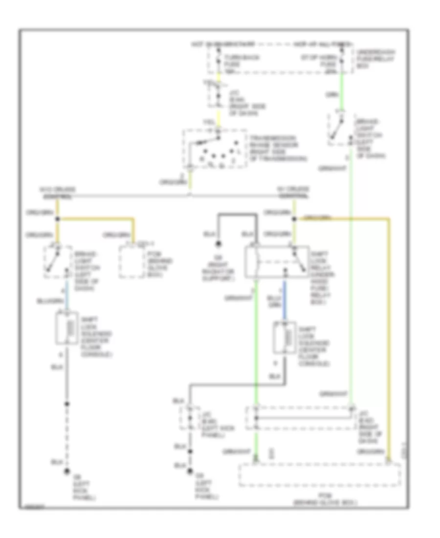
AUTOMOTIVE ELECTRICIANS PORTAL

SHIFT INTERLOCKS – Suzuki XL-7 Touring 2002 – SYSTEM WIRING DIAGRAMS

SHIFT INTERLOCKS

Shift Interlock Wiring Diagram for Suzuki XL-7 Touring 2002

Shift Interlock Wiring Diagram for Suzuki XL-7 Touring 2002 https://portal-diagnostov.com/license.html
https://portal-diagnostov.com/license.html Automotive Electricians Portal FZCO Automotive Electricians Portal FZCO
Get access to all wiring diagrams of the carDownload PDF file

List of elements for Shift Interlock Wiring Diagram for Suzuki XL-7 Touring 2002:

  • Brake- light switch (left side of dash)
  • C51-1
  • E61
  • G8 (right radiator support)
  • G9 (left kick panel)
  • Hot at all times
  • Hot in on or start
  • J/c (e42) (right side of dash)
  • J/c (e44) (right side of dash)
  • J/c (e46) (left kick panel)
  • Pcm (behind glove box)
  • Shift lock relay (under- hood fuse/ relay box)
  • Shift lock solenoid (center floor console)
  • Stop horn fuse 20a
  • Transmission range sensor (right side of transmission)
  • Turn back fuse 10a
  • Underdash fuse/relay box
  • W/ cruise control
  • W/o cruise control