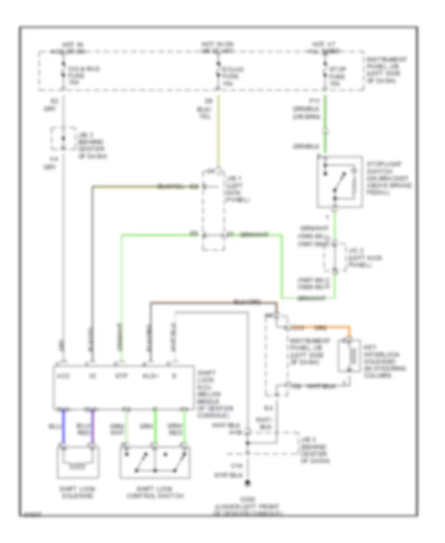
AUTOMOTIVE ELECTRICIANS PORTAL

SHIFT INTERLOCKS – Toyota Celica GT 1998 – SYSTEM WIRING DIAGRAMS

SHIFT INTERLOCKS

Shift Interlock Wiring Diagram for Toyota Celica GT 1998

Shift Interlock Wiring Diagram for Toyota Celica GT 1998 https://portal-diagnostov.com/license.html
https://portal-diagnostov.com/license.html Automotive Electricians Portal FZCO Automotive Electricians Portal FZCO
Získajte prístup ku všetkým schémam zapojenia automobiluDownload PDF file

List of elements for Shift Interlock Wiring Diagram for Toyota Celica GT 1998:

  • (1995-96) d c (1997-99)
  • (1997-99) c d (1995-96)
  • Acc
  • C10
  • C14
  • Cig & rad fuse 15a
  • Ecu-ig fuse 15a
  • F11
  • G302 (lower left front of center console)
  • Hot at all times
  • Hot in acc or on
  • Hot in on or start
  • Instrument panel j/b (left side of dash)
  • J/b 1 (left kick panel)
  • J/b 3 (behind center of dash)
  • J/c 2 (left kick panel)
  • Key interlock solenoid (in steering column)
  • Kls+
  • Shift lock control switch
  • Shift lock ecu (below middle of center console)
  • Shift lock solenoid
  • Sls+
  • Sls-
  • Stop fuse 15a
  • Stoplight switch (on bracket above brake pedal)
  • Stp