
SHIFT INTERLOCKS
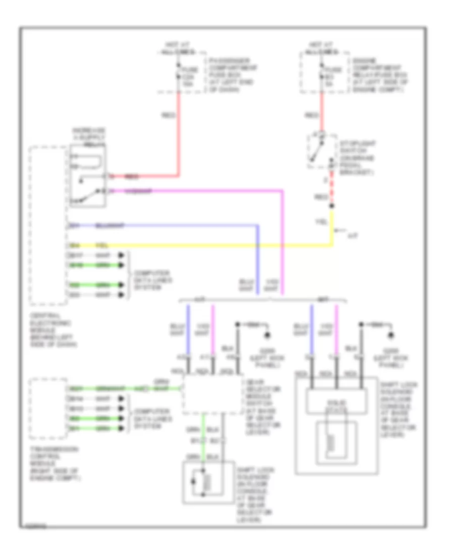
Shift Interlock Wiring Diagram for Volvo S80 T-6 1999
List of elements for Shift Interlock Wiring Diagram for Volvo S80 T-6 1999:
ANTI-LOCK BRAKESAIR CONDITIONINGANTI-THEFTBODY COMPUTERCRUISE CONTROLELECTRONIC POWER STEERINGENGINE PERFORMANCEGROUND DISTRIBUTIONEXTERIOR LIGHTSCOOLING FANDEFOGGERSHEADLIGHTSHORNCOMPUTER DATA LINESINSTRUMENT CLUSTERNAVIGATIONPOWER DOOR LOCKSPOWER MIRRORSMEMORY SYSTEMSPOWER DISTRIBUTIONINTERIOR LIGHTSPOWER WINDOWSPOWER SEATSRADIOSTARTING/CHARGINGSHIFT INTERLOCKSPOWER TOP/SUNROOFTRANSMISSIONSUPPLEMENTAL RESTRAINTSWARNING SYSTEMSWIPER/WASHER