SIERRA, SILVERADO, SUBURBAN, TAHOE & YUKON
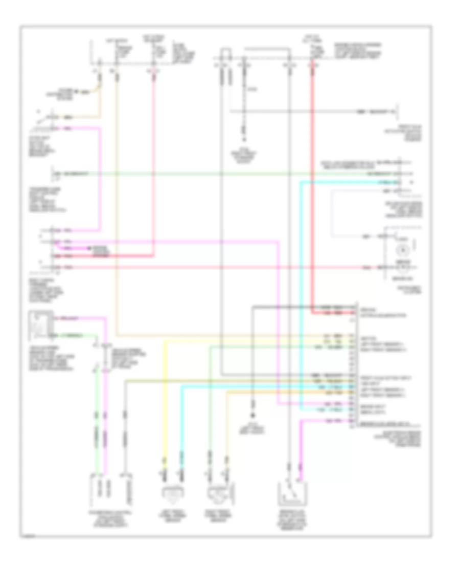
Anti-Lock Brakes Wiring Diagram (Sierra 1500/2500, Silverado 1500/2500, Suburban, Tahoe, Yukon & Yukon XL - With Traction Control) for Chevrolet Cutaway G3500 2001

List of elements for Anti-Lock Brakes Wiring Diagram (Sierra 1500/2500, Silverado 1500/2500, Suburban, Tahoe, Yukon & Yukon XL - With Traction Control) for Chevrolet Cutaway G3500 2001:
- A4 c1
- Abs fuse 60a
- Abs ind
- Body wiring harness junction block (under left side of dash, near kick panel)
- Brake fluid level sw in
- Brake fluid level switch (on left side of brake fluid reservoir)
- Brake fuse 10a
- Brake in
- Brake ind
- Brake input
- C8 a
- Data link connector (dlc) (below steering column)
- Del torque
- Delivered torque
- Electronic brake control module (ebcm) (on left side of inner frame)
- Engine wiring harness junction block (at left side of engine compt, near battery)
- F6 c3
- F7 c2
- Fuse block (on lower left side of dash)
- G113 (left front body mount)
- G132 (right front of engine block)
- G202 (upper left side of dash, at "a" pillar)
- Ground
- Ground distribution system
- Hot at all times
- Hot in run
- Hot in run or start
- Ign 1 fuse 10a
- Ignition
- Illum lamp
- Instrument cluster
- Interior lights system
- Left front sensor (+)
- Left front sensor (-)
- Left front wheel speed sensor
- Logic
- Low traction indicator
- Motor & solenoid pwr
- Nca
- Pnk
- Power distribution system
- Powertrain control module (pcm) (on left front of engine compt)
- Red
- Req torque
- Requested torque
- Right front sensor (+)
- Right front sensor (-)
- Right front wheel speed sensor
- S102
- Serial data
- Service trac cntl sig
- Sp203
- Splice pack sp203 (on top left side of dash, near "a" pillar)
- Stoplight switch (on top of brake pedal bracket)
- Tan
- Trac cntl active sig
- Trac sw input
- Traction control switch
- Traction off indicator
- Vehicle speed sensor (vss) (4wd: on top left side of transfer case) (2wd: on left rear side of transmission)
- Vehicle speed sensor adapter (4wd only) (on left side of trans)
- Vss high
- Vss input
- Vss low
- Vss out
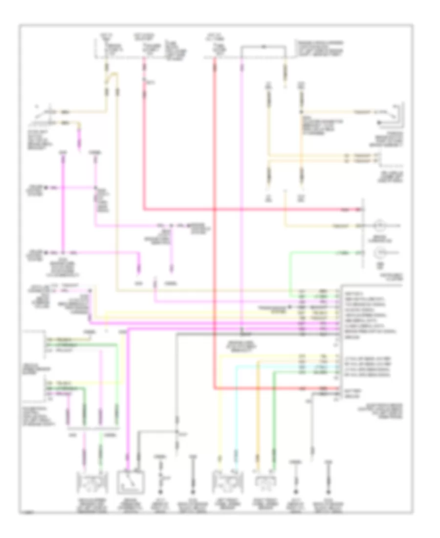
Anti-Lock Brakes Wiring Diagram (Sierra 1500/2500/2500HD, Silverado 1500/2500/2500HD, Suburban, Tahoe, Yukon & Yukon XL - Without Traction Control) for Chevrolet Cutaway G3500 2001
List of elements for Anti-Lock Brakes Wiring Diagram (Sierra 1500/2500/2500HD, Silverado 1500/2500/2500HD, Suburban, Tahoe, Yukon & Yukon XL - Without Traction Control) for Chevrolet Cutaway G3500 2001:
- A4 c1
- Abs fuse 60a
- Abs ind
- Body wiring harness junction block (under left side of dash, near kick panel)
- Brake fluid level sw in
- Brake fluid level switch (on left side of brake fluid reservoir)
- Brake fuse 10a
- Brake ind
- Brake input
- C8 a
- Data link connector (dlc) (below steering column)
- Electronic brake control module (ebcm) (on left side of inner frame)
- Engine control system
- Engine wiring harness junction block (at left side of engine compt, near battery)
- F6 c3
- F7 c2
- Front axle act/sw input
- Front axle actuator/ switch (on axle housing)
- Fuse block (on lower left side of dash)
- G113 (left front body mount)
- G132 (right front of engine block)
- Ground
- Hot at all times
- Hot in run
- Hot in run or start
- Ign 1 fuse 10a
- Ignition
- Instrument cluster
- Left front sensor (+)
- Left front sensor (-)
- Left front wheel speed sensor
- Logic
- Motor & solenoid pwr
- Nca
- Pnk
- Power distribution system
- Powertrain control module (pcm) (on left front of engine compt)
- Red
- Right front sensor (+)
- Right front sensor (-)
- Right front wheel speed sensor
- S102
- Serial data
- Splice pack sp205 (on left side of dash, behind headlamp switch)
- Stoplight switch (on top of brake pedal bracket)
- Tan
- Transfer case shift control module (left side of dash, behind headlamp switch)
- Vehicle speed sensor (vss) (4wd: on top left side of transfer case) (2wd: on left rear side of transmission)
- Vehicle speed sensor adapter (4wd only) (on left side of trans)
- Vss high
- Vss input
- Vss low
- Vss output
Anti-Lock Brakes Wiring Diagram (Sierra 3500 & Silverado 3500) for Chevrolet Cutaway G3500 2001
List of elements for Anti-Lock Brakes Wiring Diagram (Sierra 3500 & Silverado 3500) for Chevrolet Cutaway G3500 2001:
- (dlc) (below steering column)
- (engine harn, 20 cm into ebcm breakout)
- Abs fuse 60a
- Abs ind
- Abs ind failure cntl
- Abs serial data
- Axle sw signal
- Battery
- Brake fuse 18 10a
- Brake pres diff sw signal
- Brake pressure differential switch
- Brake warning ind
- Class 2 serial data
- Cruise control system
- Data link connector
- Diesel
- Drl module (under left side of dash)
- Electronic brake control module (ebcm) (on left side of inner frame)
- Engine controls system
- Engine wiring harness junction block (at left side of engine compt, near battery)
- Fuse block (on lower left side of dash)
- G117 (rear of right cyl head)
- G132 (back of engine block, below left cyl head)
- Gas
- Gauges fuse 4 10a
- Ground
- Hot at all times
- Hot in run
- Hot in run or start
- Ignition 3
- Instrument cluster
- Left front wheel speed sensor
- Lf whl sp sens low ref
- Lf whl spd sens signal
- Parking brake switch (part of park brake assembly)
- Pnk
- Powertrain control module (pcm) (on left front of engine compt)
- Red
- Rf whl sp sens low ref
- Rf whl spd sens signal
- Right front wheel speed sensor
- S107
- S150 (13 cm into ebcm breakout from engine harness)
- S152 (engine harn, 16.5 cm from evap purge valve breakout)
- S157
- S213
- S224 (cluster connector breakout, 12 cm from inflatable ip harness)
- S229 (w/a/t) (engine harn, near pcm)
- S229 (w/m/t) (i/p harn, near radio)
- Stoplight switch (on top of brake pedal bracket)
- Tan
- Tcc brake sw signal
- Transmissions system
- Vehicle speed sensor (vss) (on left side of transfer case)
- Vehicle speed sensor buffer
- Vehicle speed signal
- W/ drl
- W/o drl