POWER DISTRIBUTION
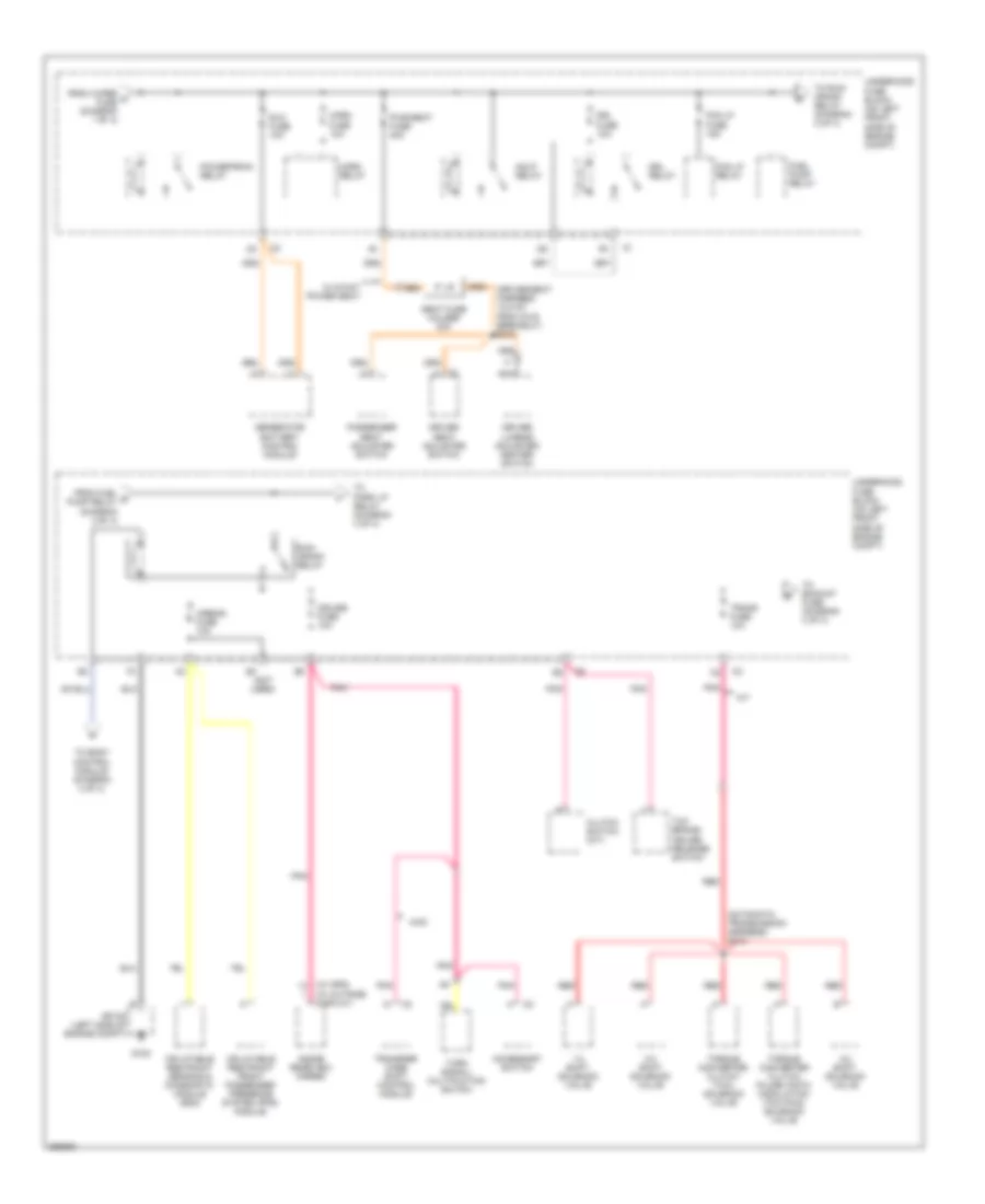
Power Distribution Wiring Diagram (1 of 4) for Isuzu i-370 LS 2007
 https://portal-diagnostov.com/license.html
Automotive Electricians Portal FZCO
Automotive Electricians Portal FZCO
https://portal-diagnostov.com/license.html
https://portal-diagnostov.com/license.html
Automotive Electricians Portal FZCO
Automotive Electricians Portal FZCO
List of elements for Power Distribution Wiring Diagram (1 of 4) for Isuzu i-370 LS 2007:
- (body harn, 4 cm from accelerator pedal position switch breakout)
- (on left front side of engine compartment) underhood fuse block
- 4wd
- A/c fuse 10a
- A10
- Abs 1 fuse 30a
- Abs 2 fuse 40a
- Air solenoid fuse block
- Aux pwr 1 fuse 20a
- Aux pwr 2 fuse 20a
- Auxiliary power outlet
- B10
- B11
- Battery
- Blower fuse 30a
- Blower motor switch
- Body control module
- C204
- Can vent fuse 10a
- Cluster fuse 10a
- Crew cab w/ power window
- Data link connector (dlc)
- Digital radio receiver
- Diode
- Door lock fuse 20a
- Driver door lock & window switch
- Driver heated seat module
- Driver lumbar adjuster/ heater switch
- E11
- Electronic brake control module
- Evaporative emission (evap) canister vent solenoid
- F12
- From a aux fuse (diagram 1 of 4)
- From turn/ b haz rr fuse (diagram 1 of 4)
- Front passenger door lock & window switch
- G106 (right side of engine compt, behind air cleaner)
- Generator
- Htd seat fuse 20a
- Hvac control module
- If equipped
- Ign 3 hvac relay
- Instrument panel cluster (ipc)
- Left rear door lock & window switch
- Mega fuse 100a
- Nca
- Onstar fuse 10a
- Passenger heated seat module
- Passenger lumbar adjuster/ heater switch
- Pcm b fuse 10a
- Powertrain control module (pcm)
- Pwr/ window fuse 30a
- Radio
- Radio fuse 15a
- Rap relay
- Red
- Regular, extended cab w/ power window
- Right rear door lock & window switch
- S101 (battery harness)
- S200
- S300 (body harness, 5 cm from g300 breakout)
- S302
- S313 (pass seat harn, 12.5cm from c318 breakout)
- S315 (driver heater element harness)
- S319 (passenger heater element harness)
- Start fuse 30a
- Start relay
- Starter
- Stop fuse 20a
- Stop lamp switch
- Sunroof fuse 20a
- Sunroof switch
- Tbc fuse 10a
- Tccm fuse 10a
- To door lock fuse (diagram 1 of 4)
- To powertrain relay (diagram 2 of 4)
- To rap relay (diagram 1 of 4)
- Transfer case shift control module
- Turn signal/ multi- function switch
- Turn/ haz fr fuse 15a
- Turn/ haz rr fuse 15a
- Underhood fuse block (on left front side of engine compartment)
- Vehicle communication interface module (vcim)
- W/ 6-way power seat
- W/ gps 1
- W/ heated seats
- Windshield wiper/washer switch
- Wip/wash fuse 10a
- Wiper fuse 25a
- Wiper relay
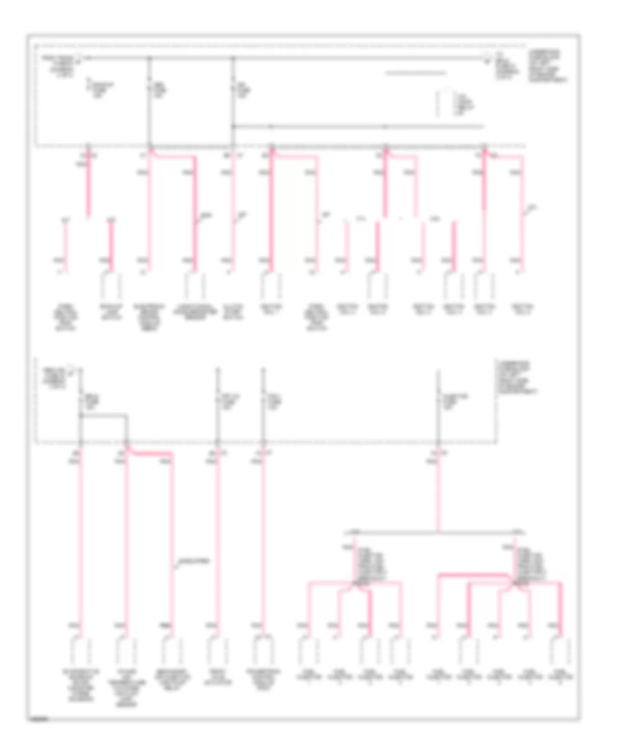
Power Distribution Wiring Diagram (2 of 4) for Isuzu i-370 LS 2007
List of elements for Power Distribution Wiring Diagram (2 of 4) for Isuzu i-370 LS 2007:
- (automatic transmission harness) s133
- (driver seat harness, 12.5 cm from c319 breakout) s312
- (not used)
- (w/ gps)
- (w/ outside display)
- 1-2 shift solenoid valve
- 2-3 shift solenoid valve
- 3-2 shift solenoid valve
- 4wd
- A/t
- Accessory switch
- Airbag fuse 10a
- Clutch switch (m/t)
- Cruise fuse 10a
- Driver lumbar adjuster/ heater switch
- Driver seat adjuster switch
- Drl fuse 10a
- Drl relay
- Fog lp fuse 15a
- Fog lp relay
- From fuel d pump relay (diagram 2 of 4)
- From wiper c fuse (diagram 1 of 4)
- Fuel pump relay
- G105
- Generator battery control module
- Hdlp relay
- Horn fuse 10a
- Horn relay
- Inflatable restraint front passenger presence system (pps) module
- Inflatable restraint sensing & diagnostic module (sdm)
- Inside rearview mirror
- Nca
- Passenger seat adjuster switch
- Pnk
- Powertrain relay
- Pwr/seat fuse 40a
- Red
- Run/ crank relay
- Rvc fuse 10a
- Seat fuse holder 20a
- Sp105 (left side of engine compt)
- Tcc brake/ cruise release switch
- To backup fuse (diagram 3 of 4)
- To body control module (diagram 4 of 4)
- To park lp relay (diagram 4 of 4)
- To run/ crank relay (diagram 2 of 4)
- Torque converter clutch (tcc) solenoid valve
- Torque converter clutch pulse width modulation (tcc pwm) solenoid valve
- Trans fuse 10a
- Transfer case shift control module
- Turn signal/ multifuction switch
- Underhood fuse block (on left front side of engine compt)
- W/ 6-way power seat
Power Distribution Wiring Diagram (3 of 4) for Isuzu i-370 LS 2007
List of elements for Power Distribution Wiring Diagram (3 of 4) for Isuzu i-370 LS 2007:
- (fuel injector harn, 4cm from fuel injector 4 breakout) s104
- (fuel injector harn, 5cm from fuel injector 4 breakout) s103
- 2.9l
- 3.7l
- 4wd
- A/c comp relay
- A/t
- Abs fuse 10a
- Back-up lamp switch
- Backup fuse 15a
- C2 b2
- C2 c3
- C2 f4
- C7 f3
- Clutch start switch
- Electronic brake control module (ebcm)
- Erls fuse 15a
- Evaporative emission (evap) canister purge solenoid
- From ign g fuse 23 (diagram 3 of 4)
- From trans e fuse 24 (diagram 2 of 4)
- Front axle actuator
- Frt ax fuse 15a
- Fuel injector
- If equipped
- Ign fuse 15a
- Ignition coil 1
- Ignition coil 2
- Ignition coil 3
- Ignition coil 4
- Ignition coil 5
- Injector fuse 15a
- Intake air temperature (iat)/mass air flow (maf) sensor
- Longitudinal accelerometer sensor
- M/t
- Park/ neutral position (pnp) switch
- Pcm i fuse 10a
- Pnk
- Pnk pnk
- Powertrain control module (pcm)
- Secondary air injection (air) pump relay
- To erls fuse 27 (diagram 3 of 4)
- Underhood fuse block (on left front side of engine compartment)
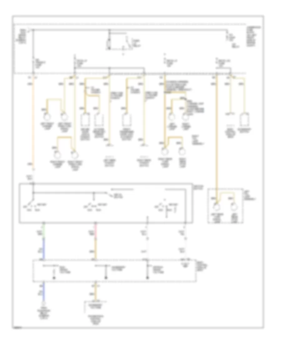
Power Distribution Wiring Diagram (4 of 4) for Isuzu i-370 LS 2007
List of elements for Power Distribution Wiring Diagram (4 of 4) for Isuzu i-370 LS 2007:
- (chassis harness, 40.5 cm from fuel pump & sender assembly breakout) s400
- 5 volt ref
- A/c comp 10a
- A/c relay
- A14
- Acc
- Accessory switch
- Accessory voltage
- Body control module (bcm)
- C1 a48
- C1 b7
- C11
- C2 a42
- C2 c
- Crew cab w/ power window
- Driver door lock & window switch
- F11
- Fr pk lp fuse 10a
- From f run/ crank relay (diagram 2 of 4)
- From run/crank relay (diagram 2 of 4)
- Front passenger door lock & window switch
- Ign trans d fuse 10a
- Ignition switch
- Key-in switch
- Left front marker lamp
- Left front park/turn signal lamp
- Left license lamp
- Left rear stop lamp
- Left rear turn signal lamp
- Left rear window switch
- Left tail lamp assembly
- Off
- Off/run/ crank voltage
- Outside rearview mirror switch
- Park lp relay
- Powertrain control module (pcm)
- Right front marker lamp
- Right front park/turn signal lamp
- Right license lamp
- Right rear stop lamp
- Right rear turn signal lamp
- Right rear window switch
- Right tail lamp assembly
- Rr pk lp fuse 15a
- Rr pk lp2 fuse 10a
- Run
- Run/ crank voltage
- S900 (license lamp harness, 44.5cm before right license lamp)
- Start
- Underhood fuse block (on left front side of engine compt)
- W/ power window

 Čeština
 Dansk
Dansk Deutsch
 Ελληνικά
 English
 English
 Español
 Suomi
Suomi Français
 Français
 עברית
עברית Hrvatski
 Magyar
 Italiano
 日本語
日本語 한국어
한국어 Nederlands
 Polski
 Português
 Português
 Română
 Русский
 Slovenščina
 Svenska
 Türkçe
 中文 (中国)