SUPPLEMENTAL RESTRAINTS
Supplemental Restraints Wiring Diagram (1 of 2) for Hummer H3 2010
 https://portal-diagnostov.com/license.html
Automotive Electricians Portal FZCO
Automotive Electricians Portal FZCO
https://portal-diagnostov.com/license.html
https://portal-diagnostov.com/license.html
Automotive Electricians Portal FZCO
Automotive Electricians Portal FZCO
List of elements for Supplemental Restraints Wiring Diagram (1 of 2) for Hummer H3 2010:
- Driver seat belt pretensioner (at left inner "b" pillar)
- G310 (mounted under left side of passenger seat)
- Gnd
- Hot w/ run/crank relay energized
- I/p multi-function switch
- I/p stage 1-hi
- I/p stage 1-lo
- I/p stage 2-hi
- I/p stage 2-lo
- Ignition voltage
- Inflatable restraint i/p module (above dash compartment)
- Inflatable restraint passenger air bag on/off indicator
- Inflatable restraint sensing & diagnostic module (sdm) (beneath lower console)
- Inflatable restraint steering wheel module (in steering column)
- Inflatable restraint steering wheel module coil (mounted to steering wheel)
- J310
- Lh asf sig
- Lh asf volt
- Lh asf-hi
- Lh asf-lo
- Lh belt sw
- Lh pretens-hi
- Lh pretens-lo
- Lh sens sig
- Lh sens volt
- Nca
- Off
- Passenger seat belt indicator
- Passenger seat belt pretensioner (at right inner "b" pillar)
- Pin shorting bars engaged
- Pnk
- Red
- Rh asf sig
- Rh asf volt
- Rh asf-hi
- Rh asf-lo
- Rh belt sw
- Rh pretens-hi
- Rh pretens-lo
- Rh sens sig
- Rh sens volt
- Serial data
- Serial data link
- Shorting bar
- Sir fuse 27 10a
- Stage 1
- Stage 1-hi ctrl
- Stage 1-lo ctrl
- Stage 2
- Stage 2-hi
- Stage 2-lo
- Tan
- Underhood fuse block (above left front wheelwell)
- When module connector is disconnected from harness (shorting bars are connected between pins: 4-5, 8-9, 16-17, 18-19, 6-7, 10-11, 12-13 & 14-15)
- X200
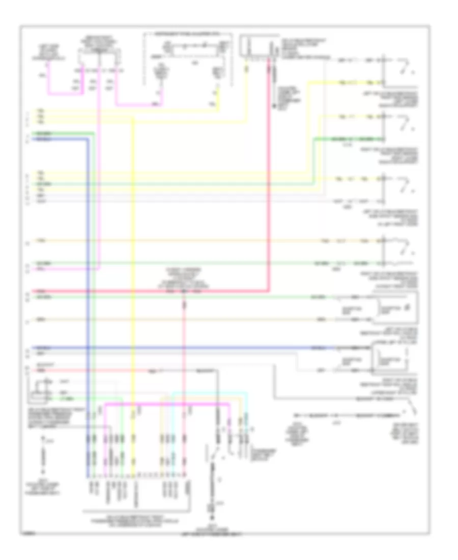
Supplemental Restraints Wiring Diagram (2 of 2) for Hummer H3 2010
List of elements for Supplemental Restraints Wiring Diagram (2 of 2) for Hummer H3 2010:
- (behind right front kick panel) body control module
- (in body harness, approximately 13 cm right of breakout to g310) (w/ head curtain air bag) j323
- (left side of dash) data link connector (dlc)
- (mounted under left side of passenger seat) g310
- (upper left "b" pillar)
- A39 x2
- A42 x1
- Air bag ind
- Driver seat belt switch (part of seat belt buckle (driver))
- G310 (mounted under left side of passenger seat)
- Gnd
- Ign
- Ign volt
- Ignition volt
- Inflatable restraint front passenger presence system (pps) module (on underside of cushion)
- Inflatable restraint front passenger presence system (pps) sensor (in front passenger seat cushion)
- Inflatable restraint vehicle rollover sensor (w/ roof) (under center console)
- Instrument panel cluster (ipc)
- Ipc class 2 serial data
- J310
- Left inflatable restraint front end sensor (left lower radiator support)
- Left inflatable restraint roof rail module (w/ roof)
- Left inflatable restraint side impact sensor (sis) (w/ roof) (in left front door)
- Logic
- Low ref
- Nca
- Off ind
- On ind
- Passenger seat belt buckle
- Pnk
- Press sig
- Red
- Right inflatable restraint front end sensor (right lower radiator support)
- Right inflatable restraint roof rail module (w/ roof) (upper right "b" pillar)
- Right inflatable restraint side impact sensor (sis) (w/ roof) (in right front door)
- Seat belt ind
- Serial
- Shorting bar
- Tan
- Tension sig
- Volt ref
- X115
- X2 a38
- X315
- X500
- X600

 Čeština
 Dansk
Dansk Deutsch
 Ελληνικά
 English
 English
 Español
 Suomi
Suomi Français
 Français
 עברית
עברית Hrvatski
 Magyar
 Italiano
 日本語
日本語 한국어
한국어 Nederlands
 Polski
 Português
 Português
 Română
 Русский
 Slovenščina
 Svenska
 Türkçe
 中文 (中国)