
 Čeština
 Dansk
Dansk Deutsch
 Ελληνικά
 English
 English
 Español
 Suomi
Suomi Français
 Français
 עברית
עברית Hrvatski
 Magyar
 Italiano
 日本語
日本語 한국어
한국어 Nederlands
 Polski
 Português
 Português
 Română
 Русский
 Slovenščina
 Svenska
 Türkçe
 中文 (中国)

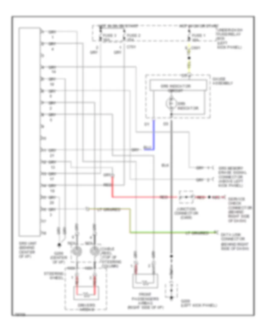
SUPPLEMENTAL RESTRAINTS
Supplemental Restraint Wiring Diagram for Isuzu Oasis LS 1996
List of elements for Supplemental Restraint Wiring Diagram for Isuzu Oasis LS 1996:

AIR CONDITIONINGANTI-LOCK BRAKESCOMPUTER DATA LINESANTI-THEFTCRUISE CONTROLDEFOGGERSCOOLING FANEXTERIOR LIGHTSENGINE PERFORMANCEGROUND DISTRIBUTIONINSTRUMENT CLUSTERHORNHEADLIGHTSPOWER MIRRORSPOWER DISTRIBUTIONPOWER DOOR LOCKSPOWER SEATSPOWER WINDOWSINTERIOR LIGHTSRADIOSHIFT INTERLOCKSSTARTING/CHARGINGPOWER TOP/SUNROOFSUPPLEMENTAL RESTRAINTSWARNING SYSTEMSTRANSMISSIONWIPER/WASHER