
 Čeština
 Dansk
Dansk Deutsch
 Ελληνικά
 English
 English
 Español
 Suomi
Suomi Français
 Français
 עברית
עברית Hrvatski
 Magyar
 Italiano
 日本語
日本語 한국어
한국어 Nederlands
 Polski
 Português
 Português
 Română
 Русский
 Slovenščina
 Svenska
 Türkçe
 中文 (中国)

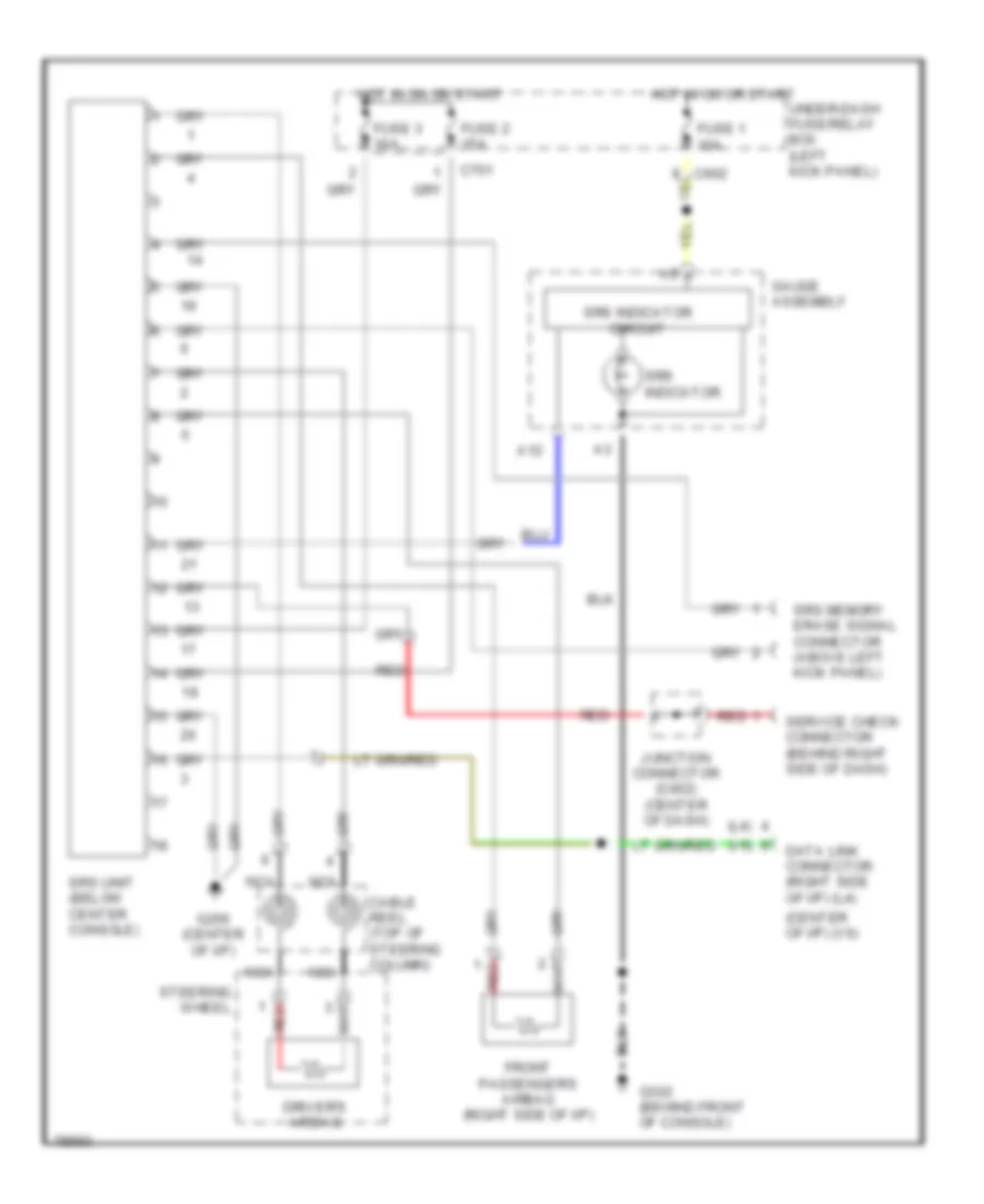
SUPPLEMENTAL RESTRAINTS
Supplemental Restraint Wiring Diagram for Honda Accord LX 1995
List of elements for Supplemental Restraint Wiring Diagram for Honda Accord LX 1995:

ANTI-LOCK BRAKESCOMPUTER DATA LINESCRUISE CONTROLCOOLING FANAIR CONDITIONINGDEFOGGERSHEADLIGHTSHORNGROUND DISTRIBUTIONENGINE PERFORMANCEINTERIOR LIGHTSANTI-THEFTINSTRUMENT CLUSTEREXTERIOR LIGHTSPOWER MIRRORSPOWER DISTRIBUTIONPOWER DOOR LOCKSPOWER ANTENNARADIOPOWER SEATSPOWER TOP/SUNROOFPOWER WINDOWSSHIFT INTERLOCKSSTARTING/CHARGINGSUPPLEMENTAL RESTRAINTSTRANSMISSIONWARNING SYSTEMSWIPER/WASHER