БЛОК ПРЕДОХРАНИТЕЛЕЙ И РЕЛЕ
Электросхема блока предохранителей и реле (1 из 4) для Ford Ranger 2000
 https://portal-diagnostov.com/license.html
Automotive Electricians Portal FZCO
Automotive Electricians Portal FZCO
https://portal-diagnostov.com/license.html
https://portal-diagnostov.com/license.html
Automotive Electricians Portal FZCO
Automotive Electricians Portal FZCO
Электросхема блока предохранителей и реле (1 из 4) для Ford Ranger 2000 - Список элементов:
- (main harness, near breakout for radio) s218
- 4wabs control module
- Accessory delay relay
- Battery
- Battery junction box (left rear of engine compartment)
- Blower motor relay
- C111
- Daytime running lamps module
- Electric shift control module
- Electric shift relay
- Fog lamp relay
- From c fuse 3 (diagram 1 of 4)
- From fuse 11 b (diagram 1 of 4)
- Fuel pump relay
- Fuse 10a
- Fuse 15a
- Fuse 20a
- Fuse 30a
- Generator
- Horn relay
- Main light switch
- Maxi fuse 20a
- Maxi fuse 40a
- Maxi fuse 50a
- Mega fuse 125a
- Multi- function switch
- Nca
- Near breakout to battery junction block)
- Park lamp/ trailer tow relay
- Park lamps relay
- Pcm power relay
- Powertrain control module
- Red
- Relay box (behind dash, right of steering column)
- Remote anti-theft personality module
- S116 (dash panel to headlight jct harn, left rear of engine compartment)
- S230 (main harness, near breakout to ignition switch)
- Starter motor
- Starter motor relay
- To central junction box fuse 5 (diagram 2 of 4)
- To fuse 6 (diagram 1 of 4)
- To fuse 7 (diagram 1 of 4)
- To s232 (diagram 2 of 4)
- W/ power equipment
- W/o power equipment
- Wide open throttle/ a/c cutoff relay
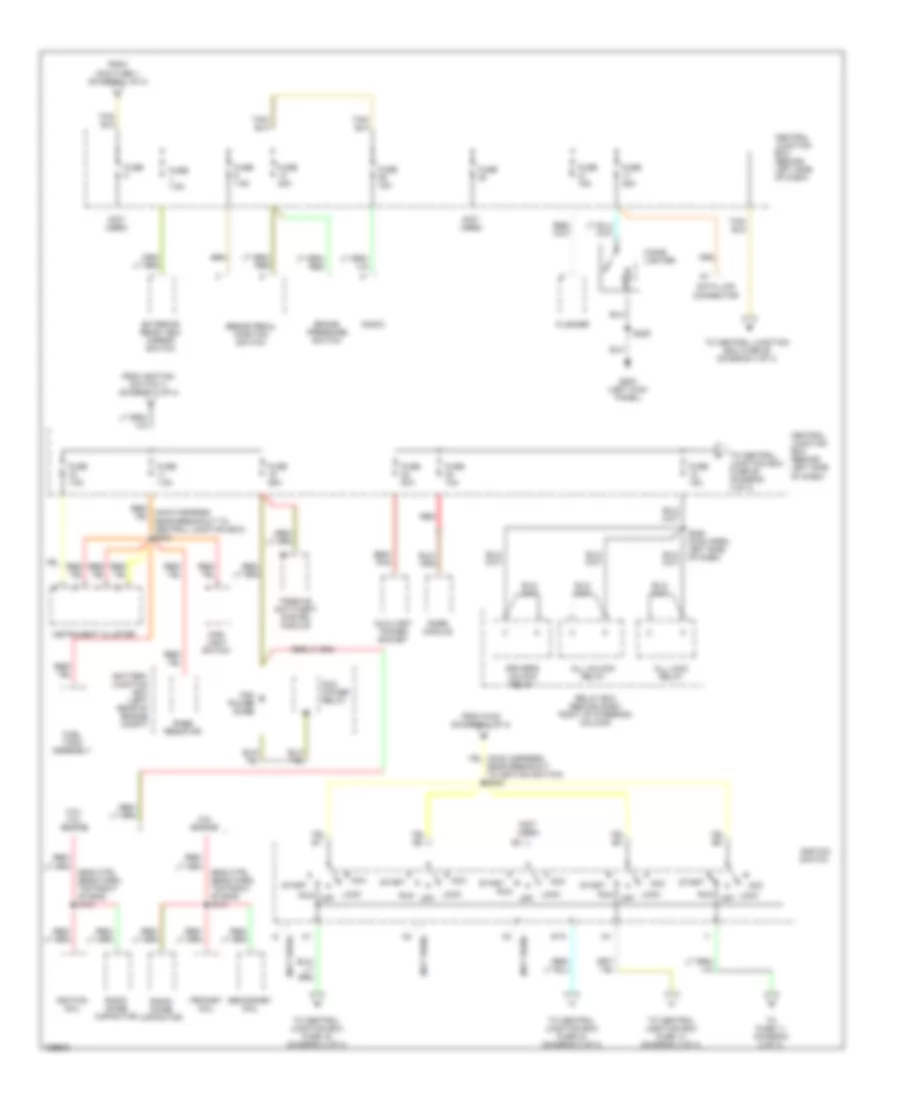
Электросхема блока предохранителей и реле (2 из 4) для Ford Ranger 2000
Электросхема блока предохранителей и реле (2 из 4) для Ford Ranger 2000 - Список элементов:
- (eng ctrl sens harn, top right of eng) s101
- (not used)
- 2.5l engine
- 3.0l/ 4.0l engine
- Acc
- All lock relay
- All unlock relay
- Auxiliary power socket
- Battery junction box (left rear of engine compt)
- Brake pedal position switch
- Brake pressure switch
- Central junction box (behind left side of dash)
- Cigar lighter
- Data link connector
- Driver's unlock relay
- Exterior rear view mirror switch
- Flasher
- From ignition switch i1 (diagram 2 of 4)
- From maxi fuse 1 (diagram 1 of 4)
- From s153 (diagram 1 of 4)
- Fuel tank assembly
- Fuse
- Fuse 10a
- Fuse 15a
- Fuse 20a
- Fuse 25a
- Fuse 7.5a
- G200 (left kick panel)
- Ignition coil
- Ignition switch
- Instrument cluster
- Lock
- Lock off
- Main light switch
- Off
- Passive anti-theft system module
- Pcm power diode
- Pcm power relay
- Primary coil
- Rabs module
- Rabs resistor
- Radio
- Radio noise capacitor
- Red
- Relay box (behind dash, right of steering column)
- Run
- S209
- S280 (main harn, left side of dash)
- Secondary coil
- Sta
- Start
- To central junction box fuse 14 (diagram 3 of 4)
- To central junction box fuse 16 (diagram 3 of 4)
- To central junction box fuse 24 (diagram 3 of 4)
- To central junction box fuse 26 (diagram 4 of 4)
- To fuse 11 (diagram 2 of 4)
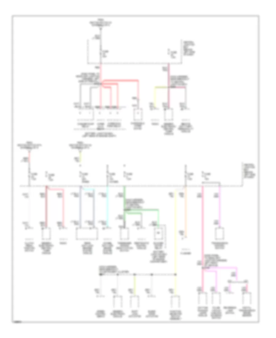
Электросхема блока предохранителей и реле (3 из 4) для Ford Ranger 2000
Электросхема блока предохранителей и реле (3 из 4) для Ford Ranger 2000 - Список элементов:
- (dash panel to headlamp junction harness, left side of firewall) s138
- (dash panel to headlight junction harness, left front of vehicle) s126
- (main harness, near breakout to central junction box) s238
- (main harness, near breakout to central junction box) s250
- (main harness, near breakout to instrument cluster) s227
- 4wheel anti-lock brake system module
- A/t
- Battery junction box (left rear of engine compartment)
- Battery junction box (left rear of engine compt)
- Blend door actuator
- Blower motor relay
- Central junction box (behind left side of dash)
- Clutch pedal position switch
- Daytime running lamps module
- Digital transmission range sensor
- Flasher
- From ignition switch a1 (diagram 2 of 4)
- From ignition switch a4 (diagram 2 of 4)
- From ignition switch sta (diagram 2 of 4)
- Function selector switch assembly
- Fuse 10a (4wabs)
- Fuse 15a
- Fuse 20a (rabs)
- Fuse 30a
- Fuse 7.5a
- Generic electronic module
- Generic electronic/ central timer module
- M/t
- Nca
- Passenger air bag deactivation switch
- Pulse vacuum hublock solenoid switch
- Radio
- Rear anti-lock brakes system module
- Red
- Remote anti-theft personality module
- Restraints control module
- Reversing lamp switch
- Shift lock actuator
- Speed control servo
- Transmission control switch
- Washer pump relay
- Windshield wiper motor
- Wiper hi/lo relay
- Wiper run/ park relay
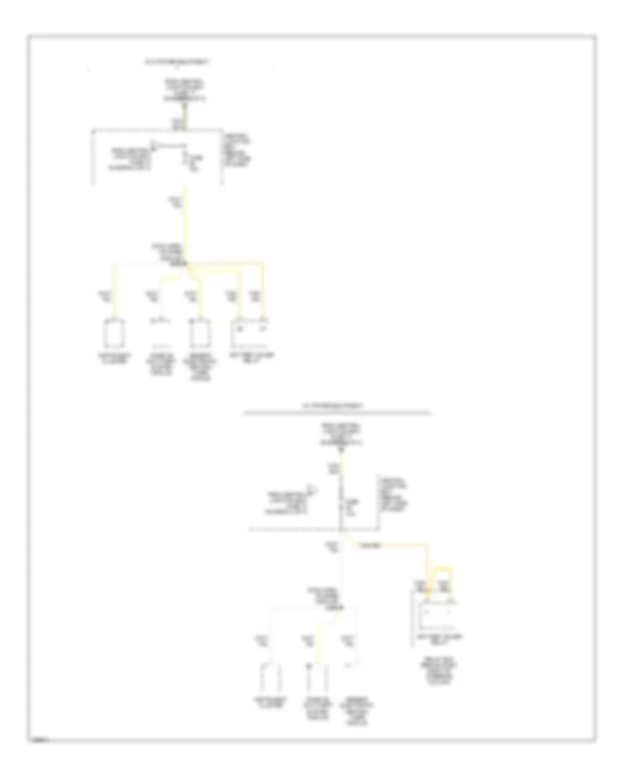
Электросхема блока предохранителей и реле (4 из 4) для Ford Ranger 2000
Электросхема блока предохранителей и реле (4 из 4) для Ford Ranger 2000 - Список элементов:
- (main harn, on rabs module) s260
- (w/ power equipment)
- (w/o power equipment)
- Battery saver relay
- Central junction box (behind left side of dash)
- F from central junction box fuse 18 (diagram 2 of 4)
- From central junction box fuse 17 (diagram 2 of 4)
- Fuse 10a
- Generic electronic/ central timer module
- Instrument cluster
- Passive anti-theft system module
- Relay box (behind dash, right of steering column)

 Čeština
 Dansk
Dansk Deutsch
 Ελληνικά
 English
 English
 Español
 Suomi
Suomi Français
 Français
 עברית
עברית Hrvatski
 Magyar
 Italiano
 日本語
日本語 한국어
한국어 Nederlands
 Polski
 Português
 Português
 Română
 Русский
 Slovenščina
 Svenska
 Türkçe
 中文 (中国)