СИСТЕМА УСИЛИТЕЛЯ РУЛЯ
Электросхема усилителя руля для Mercury Cougar XR7 1997
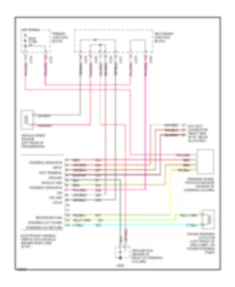
Электросхема усилителя руля для Mercury Cougar XR7 1997 - Список элементов:
- (right side of i/p, above glove box)
- C226
- C232
- C233
- C236
- C237
- C238
- C240
- Electronic variable orifice (evo) module (behind right side of i/p)
- Evo test connector
- G205
- Ground
- Ground bus (behind i/p, right of steering column)
- Hot in run
- Ign
- Input
- Module gnd
- Power steering actuator (left front of eng compt, on power steering pump)
- Primary junction block
- Red
- Run fuse 5a
- Secondary junction block
- Sensor return
- Steering act power
- Steering act return
- Steering sensor in
- Steering wheel rotation sensor (on base of steering column)
- Test terminal
- Vehicle speed sensor (left rear of transmission)
- Vss gnd
- Vss in
 Čeština
 Dansk
Dansk Deutsch
 Ελληνικά
 English
 English
 Español
 Suomi
Suomi Français
 Français
 עברית
עברית Hrvatski
 Magyar
 Italiano
 日本語
日本語 한국어
한국어 Nederlands
 Polski
 Português
 Português
 Română
 Русский
 Slovenščina
 Svenska
 Türkçe
 中文 (中国)
 Slovenčina