STARTING/CHARGING
Charging Wiring Diagram for Isuzu i-370 LS 2007


List of elements for Charging Wiring Diagram for Isuzu i-370 LS 2007:
- (not used)
- A11 c2
- B+ s
- B11
- Batt pos volt
- Battery
- Class 2 serial data
- Computer data lines system
- Field duty cyc
- G100 (next to rear side of battery)
- G102 (lower left side of engine)
- G104 (left side of engine)
- Gen reg cntrl
- Gen turn on
- Generator
- Generator battery control module (left front of engine compt, near battery)
- Ground
- Instrument panel cluster (ipc)
- Logic
- Mega fuse fuse 100a
- Powertrain control module (pcm) (right rear corner of engine compt)
- Red
- Rvc fuse 10a
- S105
- Serial data
- Starter solenoid
- Underhood fuse block (on left front side of engine compt)
- Volts
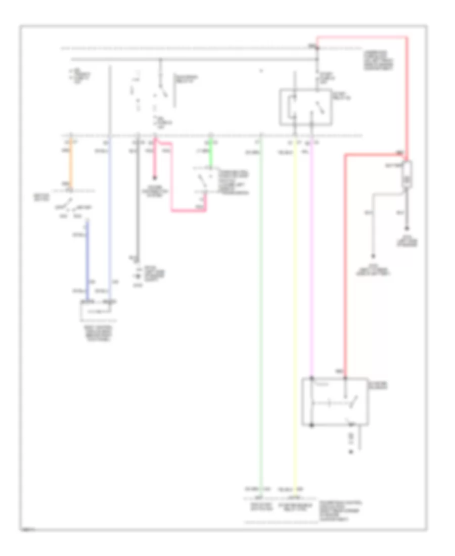
Starting Wiring Diagram for Isuzu i-370 LS 2007
List of elements for Starting Wiring Diagram for Isuzu i-370 LS 2007:
- Acc
- Battery
- Body control module (bcm) (behind right kick panel)
- C1 b6
- C2 b8
- C2 d2
- C2 e2
- C6 f3
- C7 c3
- C7 d1
- G100 (next to rear side of battery)
- G104 (left side of engine)
- G105
- Ign fuse 23 15a
- Ign trans d fuse 10 10a
- Ignition switch
- Off
- Park/neutral position (pnp) switch (lower left side of transmission)
- Pnk
- Pnp start switch sig
- Power distribution system
- Powertrain control module (pcm) (right rear corner of engine compartment)
- Red
- Run
- Run/crank relay 61
- Sp105 (left side of engine compt)
- Start
- Start fuse 43 30a
- Start relay 62
- Starter enable relay ctrl
- Starter solenoid
- Underhood fuse block (on left front side of engine compartment)

 Čeština
 Dansk
Dansk Deutsch
 Ελληνικά
 English
 English
 Español
 Suomi
Suomi Français
 Français
 עברית
עברית Hrvatski
 Magyar
 Italiano
 日本語
日本語 한국어
한국어 Nederlands
 Polski
 Português
 Português
 Română
 Русский
 Slovenčina
 Svenska
 Türkçe
 中文 (中国)