СИСТЕМА ПЕРЕДАЧИ ДАННЫХ
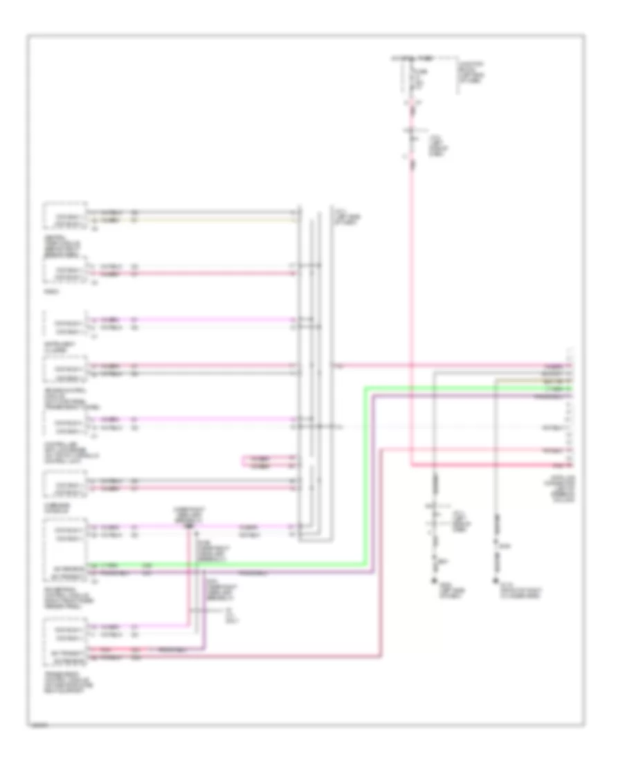
Электросхема компьютерной линии передачи данных CAN для Dodge Dakota R/T 2000
Электросхема компьютерной линии передачи данных CAN для Dodge Dakota R/T 2000 - Список элементов:
- (near right headlamp breakout) s190
- Air bag control module (on floor panel transmission tunnel)
- Ccd bus (+)
- Ccd bus (-)
- Central timer module (behind right side of dash)
- Controller anti-lock brake (on top of hydraulic control unit)
- D20
- D21
- D22
- Data link connector (left of steering column)
- Fuse 15a
- G119 (front of right cylinder head)
- G202 (left side of dash)
- Hot at all times
- Instrument cluster
- J/c 3 (left side of dash)
- J/c 4 (left side of dash)
- Junction block (left end of dash)
- Overhead console
- Pnk
- Powertrain control module (right front inner fender panel)
- Radio
- S105
- S189 (near right headlamp breakout)
- S191 (near right headlamp breakout)
- S201
- Sci receive
- Sci transmit
- Transmission control module (on radiator core right support)
- W/ 4.7l only
 Čeština
 Dansk
Dansk Deutsch
 Ελληνικά
 English
 English
 Español
 Suomi
Suomi Français
 Français
 עברית
עברית Hrvatski
 Magyar
 Italiano
 日本語
日本語 한국어
한국어 Nederlands
 Polski
 Português
 Português
 Română
 Русский
 Slovenčina
 Svenska
 Türkçe
 中文 (中国)
 Slovenščina