SUPPLEMENTAL RESTRAINTS
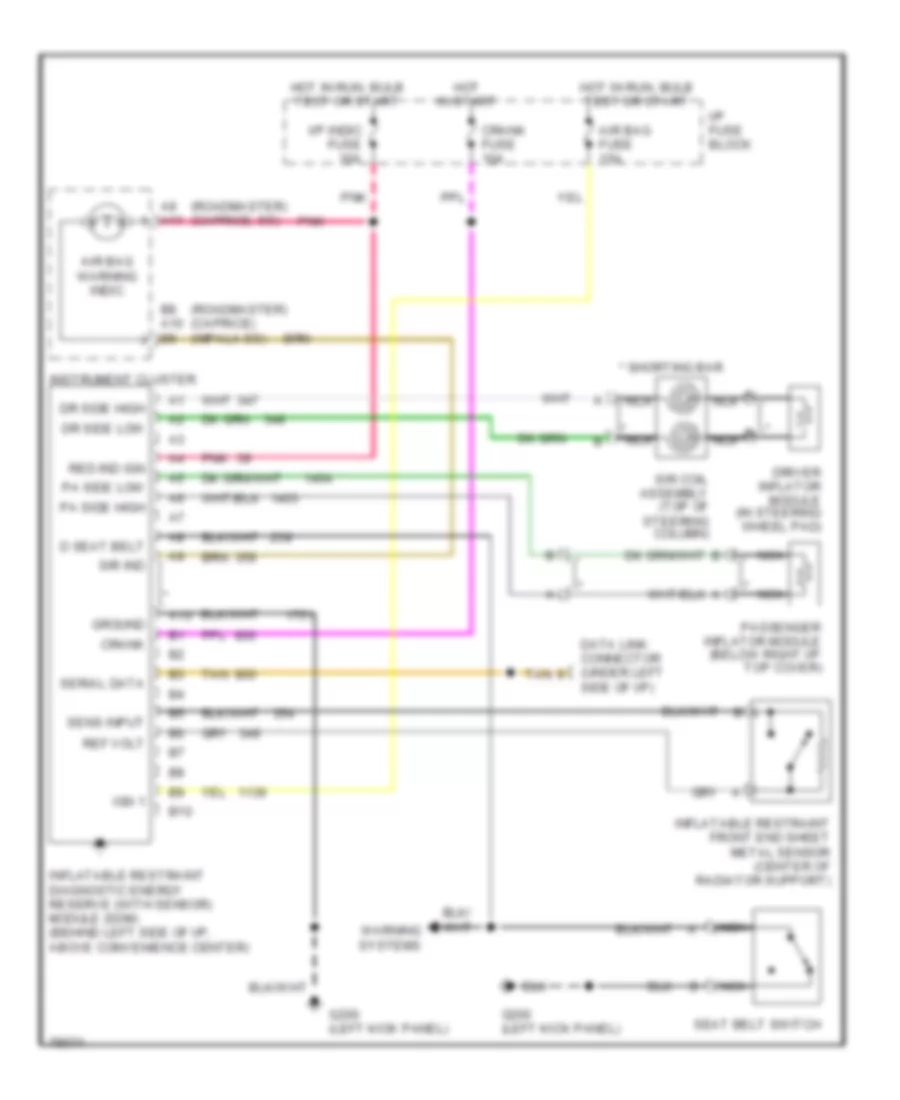
Supplemental Restraint Wiring Diagram for Buick Roadmaster Estate Wagon 1996
List of elements for Supplemental Restraint Wiring Diagram for Buick Roadmaster Estate Wagon 1996:
- (roadmaster) (caprice) (impala ss)
- (roadmaster) (caprice, ss)
- * b
- * nca
- * shorting bar
- A10
- A9 a11
- Air bag fuse 15a
- Air bag warning indic
- B10
- B8 a10 b9
- Crank
- Crank fuse 10a
- D seat belt
- Data link connector (under left side of i/p)
- Dr side high
- Dr side low
- Driver inflator module (in steering wheel pad)
- G200 (left kick panel)
- Ground
- Hot in run, bulb test or start
- Hot in start
- I/p fuse block
- I/p indic fuse 10a
- Ign 1
- Inflatable restraint diagnostic energy reserve (with sensor) module (sdm) (behind left side of i/p, above convenience center)
- Inflatable restraint front end sheet metal sensor (center of radiator support)
- Instrument cluster
- Nca
- Pa side high
- Pa side low
- Passenger inflator module (below right i/p top cover)
- Pnk
- Red ind ign
- Ref volt
- Seat belt switch
- Sens input
- Serial data
- Sir coil assembly (top of steering column)
- Sir ind
- Tan
- Warning systems
 Čeština
 Dansk
Dansk Deutsch
 Ελληνικά
 English
 English
 Español
 Suomi
Suomi Français
 Français
 עברית
עברית Hrvatski
 Magyar
 Italiano
 日本語
日本語 한국어
한국어 Nederlands
 Polski
 Português
 Português
 Română
 Русский
 Slovenčina
 Svenska
 Türkçe
 中文 (中国)
 Slovenščina