SHIFT INTERLOCK
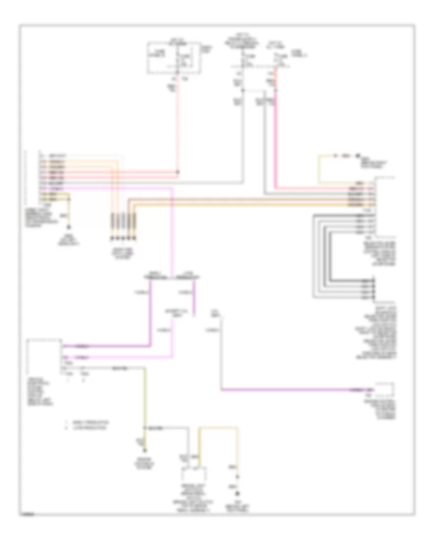
Shift Interlock Wiring Diagram for Audi A3 Quattro 2009
List of elements for Shift Interlock Wiring Diagram for Audi A3 Quattro 2009:
- 14a
- 2.0l cbfa
- Brake light switch & brake pedal switch (brake light switch: top of brake pedal assembly)
- Computer data lines system
- Direct shift gearbox (dsg) mechatronic (on transmission housing)
- E-box high
- Early production
- Engine control module (ecm) (in center of plenum chamber)
- Engine controls system
- Except 2.0l cbfa
- Fuse 10a
- Fuse 15a
- Fuse panel b
- Fuse panel c
- G44 (behind left kick panel)
- G638 (behind right kick panel)
- G655 (on left headlight)
- Hot at all times
- Late production
- Nca
- Selector lever sensor system control module (left side of selector lever base)
- Shift lock solenoid & selector lever park position lock switch (shift lock solenoid: front of selector lever base) (selector lever park position lock switch: forward of gear selector assembly)
- T10k
- T16a
- T20e
- T26
- T4r
- T52c
- T94
- Vehicle electrical system control module (below left side of dash)
 Čeština
 Dansk
Dansk Deutsch
 Ελληνικά
 English
 English
 Español
 Suomi
Suomi Français
 Français
 עברית
עברית Hrvatski
 Magyar
 Italiano
 日本語
日本語 한국어
한국어 Nederlands
 Polski
 Português
 Português
 Română
 Русский
 Slovenčina
 Svenska
 Türkçe
 中文 (中国)
 Slovenščina