INSTRUMENT CLUSTER
Instrument Cluster Wiring Diagram for Mazda B3000 Dual Sport 2005
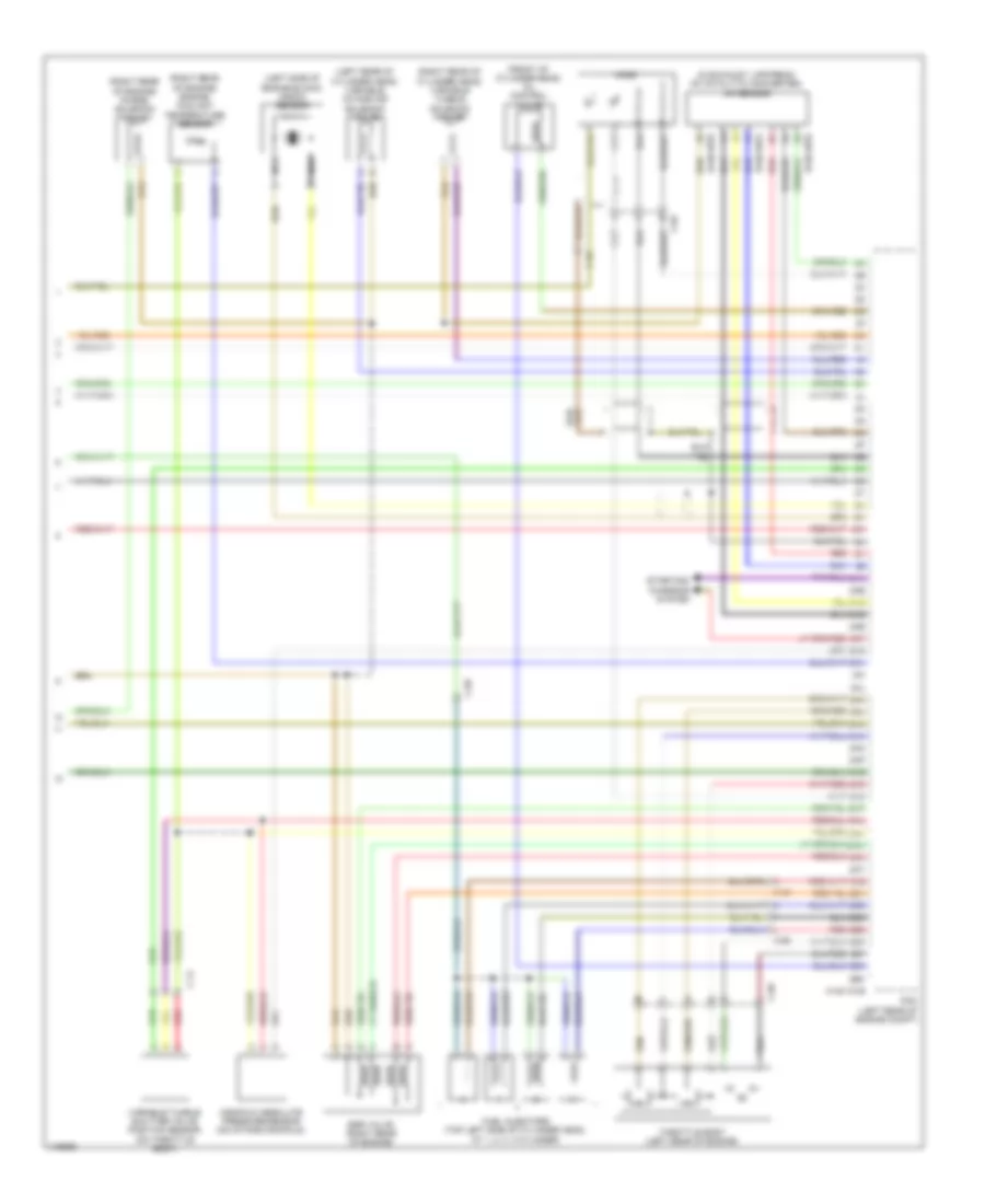
List of elements for Instrument Cluster Wiring Diagram for Mazda B3000 Dual Sport 2005:
- (front of cylinder head) oil control valve
- (in exhaust, upstream of catalytic converter) a/f sensor
- (left rear of cylinder head) variable intake air solenoid valve
- (left side of engine block) knock sensor
- (right rear of cylinder head) variable tumble solenoid valve
- (right rear of engine) engine coolant temperature sensor
- (right rear of engine) purge solenoid valve
- 0140-101b
- 0140-107a
- 0140-107b
- 2aa
- 2ab
- 2ac
- 2ad
- 2ae
- 2af
- 2ag
- 2ah
- 2ai
- 2aj
- 2ak
- 2al
- 2am
- 2an
- 2ao
- 2ap
- 2aq
- 2ar
- 2as
- 2at
- 2au
- 2av
- 2aw
- 2ax
- 2ay
- 2az
- 2ba
- 2bb
- 2bc
- 2bd
- 2be
- 2bf
- 2bg
- 2bh
- C-02
- C-14
- C-69
- Egr valve (right rear of engine)
- Fuel injectors (top left side of cylinder head, at 1, 2, 3, 4 cylinder)
- Ho2s
- Manifold absolute pressure sensor (on intake manifold)
- Nca
- Pcm (left rear of engine compt)
- Red
- Starting/ charging system
- Throttle body (left rear of engine)
- Variable tumble shutter valve position sensor (on throttle body)
 Čeština
 Dansk
Dansk Deutsch
 Ελληνικά
 English
 English
 Español
 Suomi
Suomi Français
 Français
 עברית
עברית Hrvatski
 Magyar
 Italiano
 日本語
日本語 한국어
한국어 Nederlands
 Polski
 Português
 Português
 Română
 Русский
 Slovenčina
 Svenska
 Türkçe
 中文 (中国)
 Slovenščina