AIR CONDITIONING
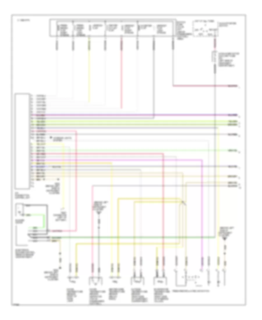
Air Conditioning Wiring Diagrams (1 of 2) for Mercedes-Benz E300 1995
List of elements for Air Conditioning Wiring Diagrams (1 of 2) for Mercedes-Benz E300 1995:
- (behind left
- (right side of steering column)
- A/c blower motor auxiliary fuse 30a (left side of component compartment)
- A/c pushbutton control unit
- Acc
- Blower motor
- C 1995 vftc
- Center outlet flap
- Cluster)
- Defrost flap long stroke
- Defrost flap short stroke
- Diverter flap
- Electronic blower control (rear of engine compartment)
- Evaporator temperature sensor
- Fresh/ recirc flap long stroke
- Fresh/ recirc flap short stroke
- Fresh/recirculated air switch
- G202
- G202 (behind left side of instrument cluster)
- Glow/starter switch
- Heater core temperature sensor (below radio)
- Hot at all times
- In-car temperature sensor (part of dome lamp)
- In-car temperature sensor aspirator (top of passenger's footwell)
- Instrument
- Interior lights system
- Legroom flap
- Nca
- Off
- Outside temperature sensor (right side of component compartment)
- Run
- Side of
- Start
- Switch- over valve unit (above passenger's footwell area)
- Test connector (left of battery)
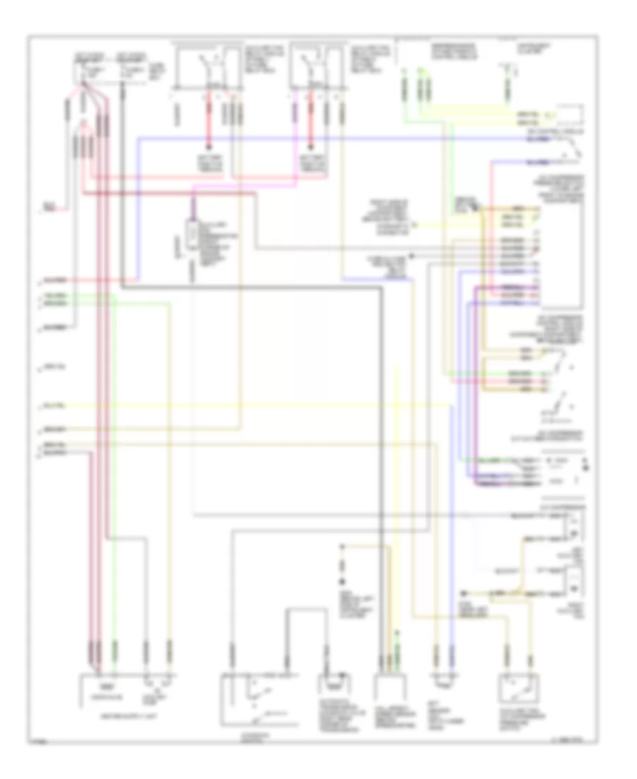
Air Conditioning Wiring Diagrams (2 of 2) for Mercedes-Benz E300 1995
List of elements for Air Conditioning Wiring Diagrams (2 of 2) for Mercedes-Benz E300 1995:
- (behind battery) g105
- (right side of component compartment, behind battery)
- 15a
- 30a
- A/c compressor
- A/c compressor control module (right side of component compartment, behind battery)
- A/c compressor cut-out/egr microswitch
- A/c compressor pressure switch (lower left front of engine compartment)
- Automatic transmission kickdown valve (right rear corner of transmission)
- Auxiliary fan preresistor (front corner of engine compart- ment)
- Auxiliary fan relay module (stage 1) (in fuse/ relay box)
- Auxiliary fan relay module (stage 2) (in fuse/ relay box)
- Auxiliary fan/ a/c compressor pressure switch
- Battery positive terminal
- C 1995 vftc
- Coolant pump
- Diagnostic connector
- Ect
- Egr/resonance intake manifold control module
- Fuse 5 8a
- Fuse 7 16a
- Fuse/ relay box
- G106 (near left headlamp)
- G202 (behind left side of instrument cluster)
- Hall effect speed sensor (behind speedometer)
- Hot in run or start
- Instrument cluster
- Isc control module
- Kickdown switch
- Left auxiliary fan
- Monovalve
- Nca
- Overvoltage protection relay module
- Red
- Right auxiliary fan
- Sensor (a/c) (on cylinder head)

 Čeština
 Dansk
Dansk Deutsch
 Ελληνικά
 English
 English
 Español
 Suomi
Suomi Français
 Français
 עברית
עברית Hrvatski
 Magyar
 Italiano
 日本語
日本語 한국어
한국어 Nederlands
 Polski
 Português
 Português
 Română
 Русский
 Slovenčina
 Svenska
 Türkçe
 中文 (中国)