ANTI-LOCK BRAKES
Anti-lock Brakes Wiring Diagram (1 of 2) for Mercedes-Benz R350 2008
 https://portal-diagnostov.com/license.html
Automotive Electricians Portal FZCO
Automotive Electricians Portal FZCO
https://portal-diagnostov.com/license.html
https://portal-diagnostov.com/license.html
Automotive Electricians Portal FZCO
Automotive Electricians Portal FZCO
List of elements for Anti-lock Brakes Wiring Diagram (1 of 2) for Mercedes-Benz R350 2008:
- (+)
- (-)
- (in left front wheelwell) w70
- (right front corner of engine compt) esp control module
- +5v
- 40a
- Ba mv
- Bas brake booster
- Can-c h
- Can-c l
- Can-h h
- Can-h l
- Computer data lines system
- Dfhl_s
- Dfhr_s
- Dfvl_s
- Dfvr_s
- Diaphragm travel sensor
- Drs s
- Drs(-)
- Drs(5v)
- Early production
- Engine compartment fuse & relay box (right side of engine compt)
- Front axle inlet solenoid valve
- Front axle switchover solenoid valve
- Front prefuse (right rear of engine compt)
- Fuse
- Fuse 25a
- Fuse 5a
- High- pressure & return pump
- Hot at all times
- Hot in on or start
- Late production
- Left front axle solenoid valve (hold)
- Left front axle solenoid valve (release)
- Left rear axle solenoid valve (release)
- Ls1
- Ls2
- Lsa
- Micromechanical turn rate sensor (on floor, under right front seat)
- Mr3
- Mr4
- Pml
- Rear axle switchover solenoid valve
- Red
- Release switch
- Right front axle solenoid valve (release)
- Right rear axle solenoid valve (release)
- Sig
- Solenoid valve
- Solenoid valve (hold) left rear axle
- Solenoid valve (hold) right front axle
- Solenoid valve (hold) right rear axle
- Solenoid valve rear axle inlet
- Sps solenoid valve (if equipped) (in left front wheelwell)
- Traction system hydraulic unit
- W70 (in left front wheelwell)
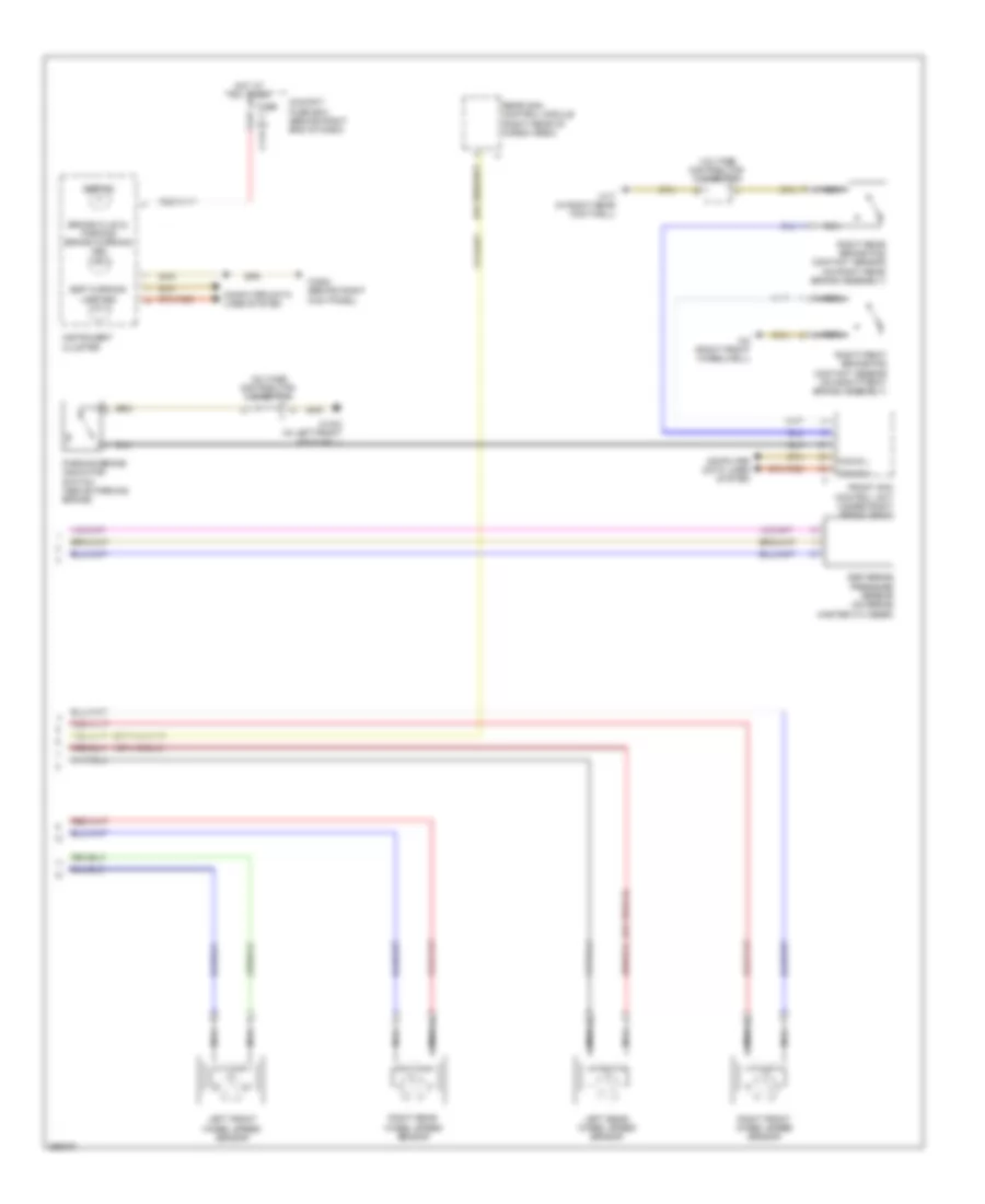
Anti-lock Brakes Wiring Diagram (2 of 2) for Mercedes-Benz R350 2008
List of elements for Anti-lock Brakes Wiring Diagram (2 of 2) for Mercedes-Benz R350 2008:
- Abs ind
- Brake fluid & parking brake warning ind
- C11a
- Can b h
- Can b l
- Cockpit fuse box (behind right end of dash)
- Computer data lines system
- Esp brake pressure sensor (on brake master cylinder)
- Esp warning lamp ind
- Front sam control unit (under right front seat)
- Fuse 5a
- Hot at all times
- Instrument cluster
- Left front wheel speed sensor
- Left rear wheel speed sensor
- Nca
- Parking brake indicator switch (above parking brake)
- Rear sam control module (right rear of cargo area)
- Right front brake pad contact sensor (on right front brake assembly)
- Right front wheel speed sensor
- Right rear brake pad contact sensor (on right rear brake assembly)
- Right rear wheel speed sensor
- Voltage distributor connector
- W15/2 (in left front footwell)
- W17 (in right rear footwell)
- W2 (right front wheelwell)
- W29/2 (behind right kick panel)

 Čeština
 Dansk
Dansk Deutsch
 Ελληνικά
 English
 English
 Español
 Suomi
Suomi Français
 Français
 עברית
עברית Hrvatski
 Magyar
 Italiano
 日本語
日本語 한국어
한국어 Nederlands
 Polski
 Português
 Português
 Română
 Русский
 Slovenčina
 Svenska
 Türkçe
 中文 (中国)