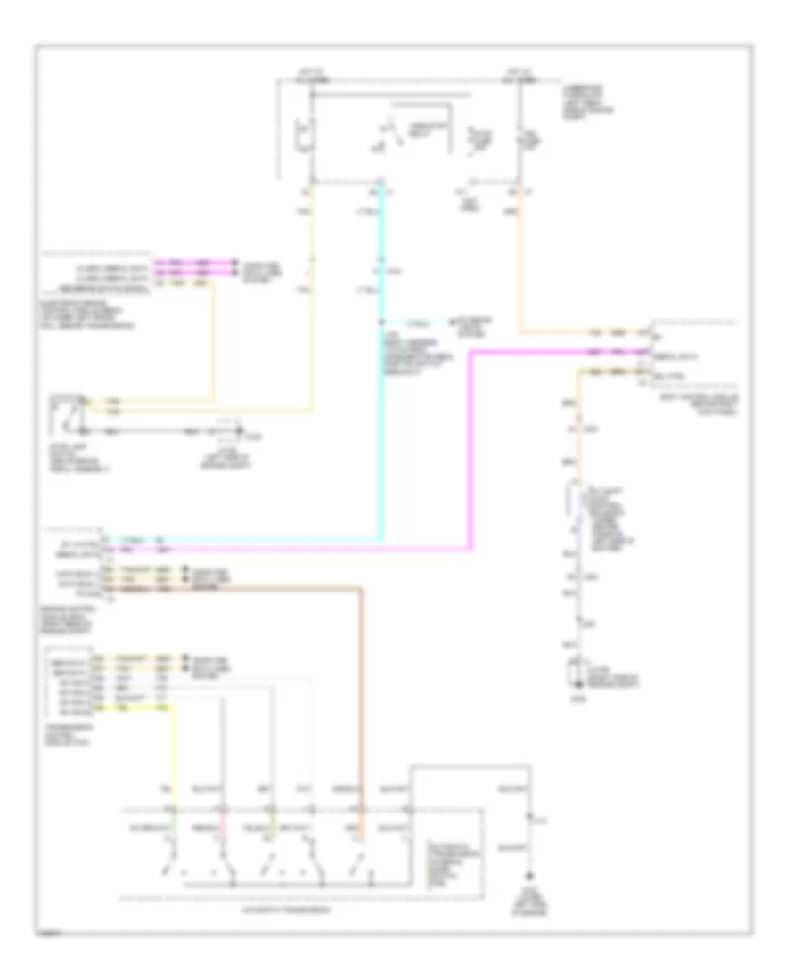
SHIFT INTERLOCK
Shift Interlock Wiring Diagram for Chevrolet Colorado 2012
List of elements for Shift Interlock Wiring Diagram for Chevrolet Colorado 2012:
- (not used)
- A/t shift lock control solenoid (under center console, left side of shifter)
- A11
- A31
- A4 x204
- A47
- Abs brake switch signal
- Automatic transmission
- Automatic transmission internal mode switch (ims)
- B2 x7
- B4 x1
- B4 x204
- Body control module (behind right kick panel)
- Class 2 serial data
- Computer data lines system
- Data bus (+)
- Data bus (-)
- Electronic brake control module (ebcm) (on inner left frame rail, beside transmission)
- Engine control module (ecm) (right rear of engine compt)
- Exterior lights system
- G102 (lower left side of engine)
- G105
- G106
- Hot at all times
- J100 (body harness, 14.5 cm from accelerator pedal position switch breakout)
- J110
- J200
- Jx105 (left side of engine compt)
- Jx106 (right side of engine compt)
- M x104
- P/n sig
- Ser data +
- Ser data -
- Serial data
- Sol ctrl
- St lp ctrl
- Stop fuse 20a
- Stop lamp switch (above brake pedal assembly)
- Sw sig a
- Sw sig b
- Sw sig c
- Sw sig p
- Tan
- Tbc fuse 10a
- Transmission control module (tcm)
- Underhood fuse block (left front side of engine compt)
- Vses/stop relay
 Čeština
 Dansk
Dansk Deutsch
 Ελληνικά
 English
 English
 Español
 Suomi
Suomi Français
 Français
 עברית
עברית Hrvatski
 Magyar
 Italiano
 日本語
日本語 한국어
한국어 Nederlands
 Polski
 Português
 Português
 Română
 Русский
 Slovenčina
 Svenska
 Türkçe
 中文 (中国)
 Slovenščina