TRANSMISSION
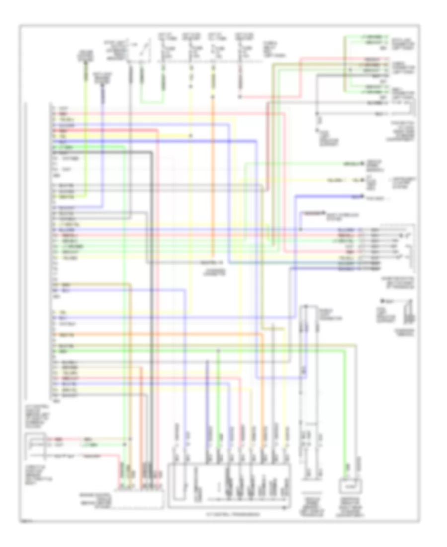
Transmission Wiring Diagram for Subaru Impreza Brighton 1996
List of elements for Transmission Wiring Diagram for Subaru Impreza Brighton 1996:
- (bottom right of transaxle)
- (right rear of engine compartment)
- A/t control (transmission)
- A/t control module (behind left i/p, right of steering column)
- A/t fluid temp indic
- Anti-lock brakes system
- Atf temperature sensor
- Awd solenoid
- B37
- B52
- B53
- B63
- B96
- B97
- Check connector (left dash)
- Cruise control system
- Data link connector (left dash)
- Diagnosis connector
- Diagnosis terminal
- Dropping resistor
- E11
- Engine control module (behind center of dash)
- Fuse & relay box (left dash)
- Fuse 10a
- Fuse 15a
- Fuse 20a
- Fwd indic
- Fwd switch (w/ awd) (right side of engine compartment)
- G108 (left radiator support)
- Hot at all times
- Hot in on or start
- Inhibitor switch
- Instrument cluster system
- Lock-up solenoid
- Nca
- Obd ii connector (left dash)
- Red
- Shield joint connector
- Shift interlock system
- Shift solenoid 1
- Shift solenoid 3
- Solenoid 2 shift
- Solenoid line pressure
- Stop light switch (on brake pedal bracket)
- Throttle position sensor (on throttle body)
- Vehicle speed sensor 1 (left side of transaxle)
- Vehicle speed sensor 2
 Čeština
 Dansk
Dansk Deutsch
 Ελληνικά
 English
 English
 Español
 Suomi
Suomi Français
 Français
 עברית
עברית Hrvatski
 Magyar
 Italiano
 日本語
日本語 한국어
한국어 Nederlands
 Polski
 Português
 Português
 Română
 Русский
 Slovenčina
 Svenska
 Türkçe
 中文 (中国)
 Slovenščina