TRANSMISSION
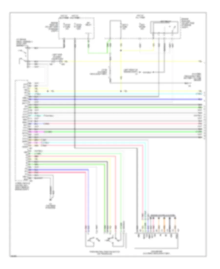
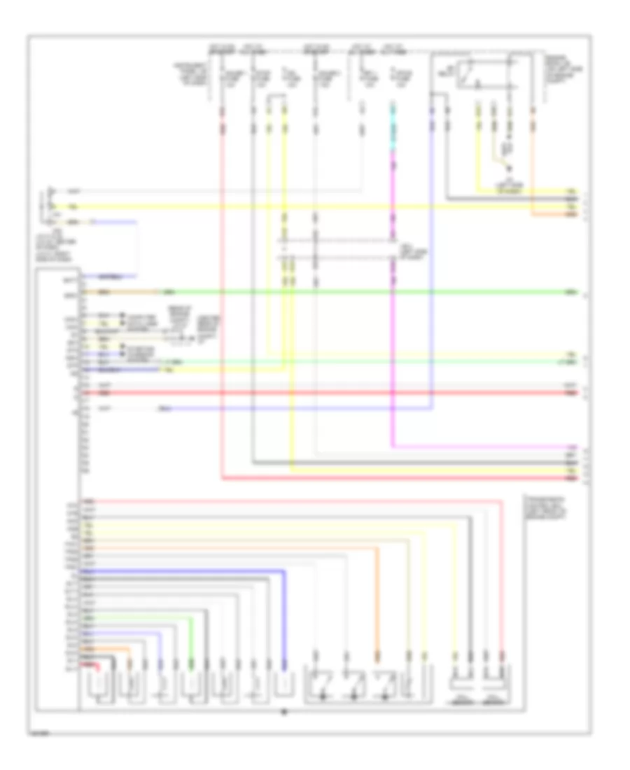
A/T Wiring Diagram, Hybrid (1 of 2) for Toyota Camry LE 2007
List of elements for A/T Wiring Diagram, Hybrid (1 of 2) for Toyota Camry LE 2007:
- (at brake pedal assembly) stop lamp switch
- (in hybrid vehicle battery) battery voltage sensor
- (left front of engine compt) a1
- (left side of dash) j/c a58 & e40
- +b1
- +b2
- +bs
- A58
- A61
- Amd
- Batt
- C4 (top rear of engine)
- C64
- Clk+
- Clk-
- Converter (in hybrid vehicle battery)
- Dc/dc fuse 120a
- E02
- E40
- Efi relay
- Engine controls system
- Engine room j/b (on left side of engine compt)
- Engine room r/b (on left side of engine compt)
- Gmt
- Gmtg
- Gnd
- Hot at all times
- Hsdn
- Htm+
- Htm-
- Hybrid vehicle control ecu (right rear of engine compt)
- Idh
- Igct
- Igct 2 fuse 10a
- Igct fuse 30a
- Igct relay
- Ilk
- In+
- In-
- J/c n6 (in hybrid vehicle battery)
- Me01
- Mmt
- Mmtg
- Mrel
- Mth+
- Mth-
- Nca
- Nodd
- Park/neutral position switch (on transaxle)
- Pnk
- Prec
- Red
- Req+
- Req-
- Smrp
- St1-
- Stop fuse 10a
- Stp
- Vlo
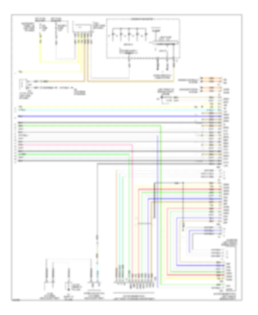
A/T Wiring Diagram, Hybrid (2 of 2) for Toyota Camry LE 2007
List of elements for A/T Wiring Diagram, Hybrid (2 of 2) for Toyota Camry LE 2007:
- (left front of engine compt) j/c a43
- +b2
- A41
- A42
- A62
- Acpb
- Acpe
- Air conditioning system
- Buzzer
- C58
- C59
- C6 (top rear of engine)
- C60
- C61
- Can i/f
- Cbi
- Cei
- Clk+
- Clk-
- Combination meter
- Computer data lines system
- D10
- Drive ic
- Drn1
- Drn2
- Drn3
- Drn4
- Drn5
- Drn6
- Drn8
- Engine controls system
- F12
- G12
- Gauge 2 fuse 7.5a
- Gcs
- Gcsg
- Gmt
- Gmtg
- Gnd
- Gnd1
- Gnd2
- Grf
- Grfg
- Gsn
- Gsng
- Hot in on or start
- Hsdn
- Htm+
- Htm-
- Ign fuse 10a
- Ilk
- Ilki
- Ilko
- Instrument panel j/b (left side of dash)
- Interlock switch (in hybrid vehicle battery)
- Inverter (left side of engine compt)
- J/b 3 (left side of dash)
- J/c a41 & a42 (left side of dash)
- J/c n6 (in hybrid vehicle battery)
- J/c o21 (rear "c" pillar)
- K12
- Mcs
- Mcsg
- Micro computer
- Mmt
- Mmtg
- Motor generator 1 (left front of engine compartment)
- Motor generator 2 (left side of engine compt)
- Mrf
- Mrfg
- Msn
- Msng
- Mth+
- Mth-
- Multi lcd
- Nca
- O1 (right "c" pillar)
- Pnk
- Red
- Req+
- Req-
2.4L
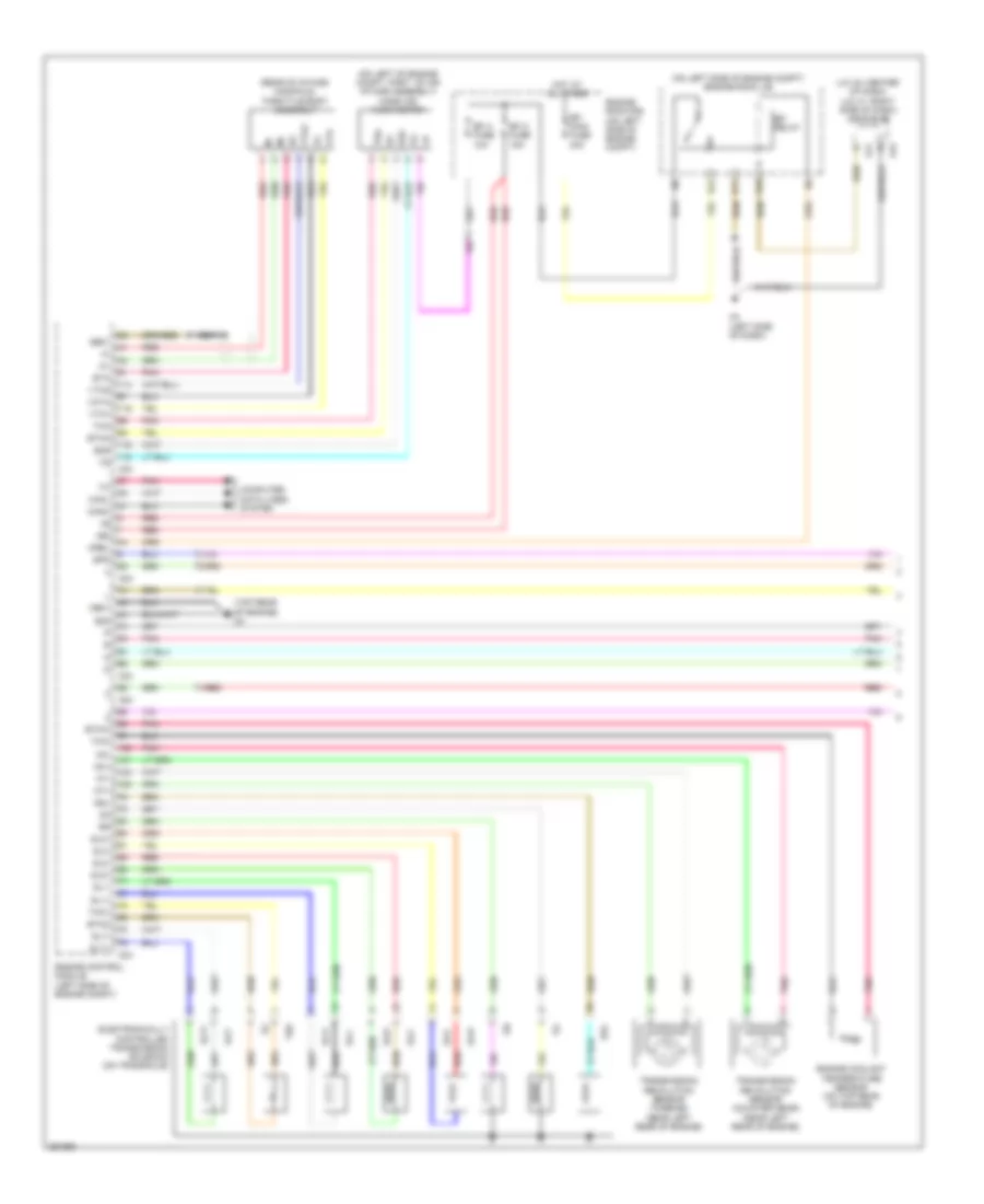
2.4L, A/T Wiring Diagram, Except Hybrid (1 of 2) for Toyota Camry LE 2007
List of elements for 2.4L, A/T Wiring Diagram, Except Hybrid (1 of 2) for Toyota Camry LE 2007:
- (j/c 42: center of dash) (j/c 41: right side of dash) j/c 41 & 42
- (on left of engine compt, part of air intake assembly) mass air flow meter
- (on left side of engine compt) engine room j/b
- (rear of intake manifold) throttle body assembly
- (top rear of engine) c4
- +b2
- A24
- A3 (left side of dash)
- A41
- A42
- C24
- Canh
- Canl
- Computer data lines system
- Dsl
- E02
- E10
- E11
- E12
- E2g
- Efi 2 fuse 15a
- Efi 3 fuse 10a
- Efi main fuse 30a
- Efi relay
- Electronically controlled transmission solenoid (on transaxle)
- Engine control module (left side of engine compt)
- Engine coolant temperature sensor (on top rear of engine)
- Engine room r/b (on left side of engine compt)
- Eta
- Etha
- Etho
- Ethw
- Ge01
- Hot at all times
- Me01
- Mrel
- Nc+
- Nc-
- Nca
- Nt+
- Nt-
- Pnk
- Red
- Sl1+
- Sl1-
- Sl2+
- Sl2-
- Sl3+
- Sl3-
- Slt+
- Slt-
- Spd
- Tha
- Tho
- Tho1
- Thw
- Transmission revolution sensor (counter gear) (near left rear of engine)
- Transmission revolution sensor (turbine) (near left rear of engine)
- Vcta
- Vta
- Vta1
- Vta2
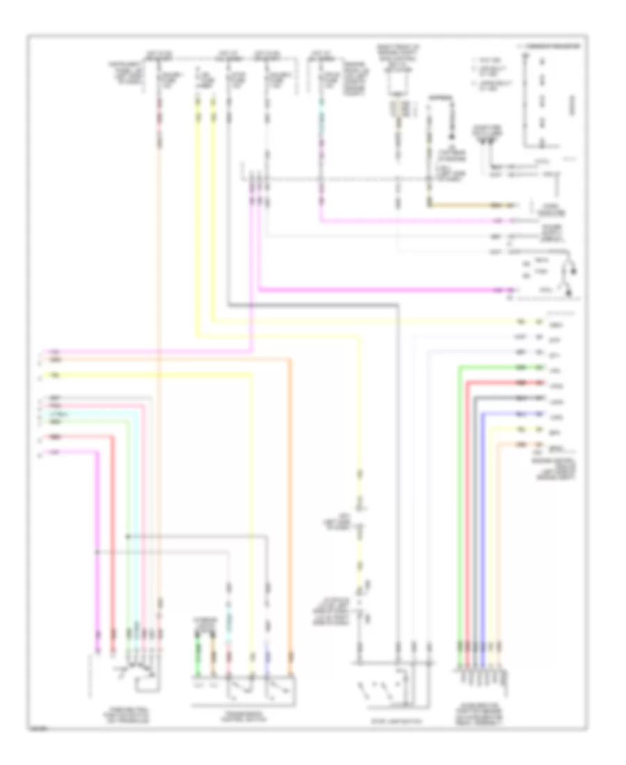
2.4L, A/T Wiring Diagram, Except Hybrid (2 of 2) for Toyota Camry LE 2007
List of elements for 2.4L, A/T Wiring Diagram, Except Hybrid (2 of 2) for Toyota Camry LE 2007:
- (right front of engine compt) skid control ecu w/ actuator
- 4,3,2,l
- A24
- A25 a60 a26
- A58
- Accelerator position sensor (on accelerator pedal assembly)
- B10
- C6 (top rear of engine)
- Can i/f
- Combination meter
- Computer
- Computer data lines system
- D10
- Drive ic
- E40
- Engine control module (left side of engine compt)
- Engine room j/b (on left side of engine compt)
- Epa
- Epa2
- F12
- G12
- Gauge 1 fuse 10a
- Gauge 2 fuse 7.5a
- H16
- Hot at all times
- Hot in on or start
- Ig2
- Ign fuse 10a
- Igsw
- Ill+
- Ill-
- Instrument panel j/b (left side of dash)
- Interior lights system
- J/b 3 (left side of dash)
- J/c 58 & 40 (j/c 58: left side of dash) (j/c 40: right side of dash)
- Japan built
- K12
- Micro
- Mpx-b fuse 10a
- P11
- Park/neutral position switch (on transaxle)
- Pnk
- Q12
- Red
- Sp1
- St1-
- Stop fuse 10a
- Stop lamp switch
- Stp
- Transmission control switch
- Usa built
- Vcp2
- Vcpa
- Vpa
- Vpa2
- W/ vsc
- W/o vsc
3.5L
3.5L, A/T Wiring Diagram, Except Hybrid (1 of 2) for Toyota Camry LE 2007
List of elements for 3.5L, A/T Wiring Diagram, Except Hybrid (1 of 2) for Toyota Camry LE 2007:
- (center rear of engine
- (rear of engine compt) j/c 57
- A3 (left side of dash)
- A41
- A42
- Batt
- Can+
- Can-
- Compt)
- Computer data lines system
- E10
- E11
- E12
- Efi 1 fuse 10a
- Efi relay
- Engine room j/b (on left side of engine compt)
- Eo1
- F12
- G12
- Gauge 1 fuse 10a
- Gauge 2 fuse 7.5a
- H16
- Hall sensor
- Hot at all times
- Hot in on or start
- Ig2
- Ign fuse 10a
- Instrument panel j/b (left side of dash)
- J/b 3 (left side of dash)
- J/c 41 & 42 (j/c 42: center of dash) (j/c 41: right side of dash)
- J12
- K12
- Mpx-b fuse 10a
- Ncb
- Nco
- Nsw
- Ntb
- Nto
- Q12
- Red
- Sl1+
- Sl1-
- Sl2+
- Sl2-
- Sl3+
- Sl3-
- Sl4+
- Sl4-
- Slt+
- Slt-
- Slu+
- Slu-
- Spd1
- Sta
- Starting/ charging system
- Stop fuse 10a
- Stp
- Tho1
- Tps1
- Tps2
- Tps3
- Transmission control ecu (left front of engine compt)
3.5L, A/T Wiring Diagram, Except Hybrid (2 of 2) for Toyota Camry LE 2007
List of elements for 3.5L, A/T Wiring Diagram, Except Hybrid (2 of 2) for Toyota Camry LE 2007:
- (center of dash) j/b 4
- (center rear of engine compt)
- (j/c 42: center of dash) (j/c 41: right side of dash) j/c 41 & 42
- +b2
- A11
- A25
- A26
- A41
- A42
- A55
- A58
- A60
- B10
- Batt
- C12
- C4 (top of engine)
- C55
- C7 (center rear of engine compt)
- Can i/f
- Can+
- Can-
- Canister pump module (left rear of vehicle)
- Combination meter
- Computer
- Computer data lines system
- D10
- Drive ic
- E04
- E40
- Ecu ig 2 fuse 7.5a
- Efi 2 fuse 15a
- Efi 3 fuse 10a
- Efi main fuse 30a
- Engine control module (behind right side of dash)
- Engine room r/b (on left side of engine compt)
- F19
- H10
- Hot at all times
- Hot in on or start
- Ig2
- Igsw
- Ill+
- Ill-
- Instrument panel j/b (left side of dash)
- Interior lights system
- J/b 3 (left side of dash)
- J/c 41 & 42 (j/c 42: center of dash) (j/c 41: right side of dash)
- J/c 57 (rear of engine compt)
- J/c 58 & 40 (j/c 58: left side of dash) (j/c 40: right side of dash)
- Japan built
- Mass air flow meter (on left of engine compt, part of air intake assembly)
- Micro
- Mrel
- P11
- Park/neutral position switch (on transaxle)
- Pnk
- Red
- Sftd
- Sftu
- Skid control ecu w/ actuator (at right side of engine compt)
- Sp1
- Spd
- St1-
- Stop lamp switch
- Stp
- Transmission control switch
- Usa built
- Vlvb
- W/ vsc
- W/o vsc

 Čeština
 Dansk
Dansk Deutsch
 Ελληνικά
 English
 English
 Español
 Suomi
Suomi Français
 Français
 עברית
עברית Hrvatski
 Magyar
 Italiano
 日本語
日本語 한국어
한국어 Nederlands
 Polski
 Português
 Português
 Română
 Русский
 Slovenčina
 Svenska
 Türkçe
 中文 (中国)