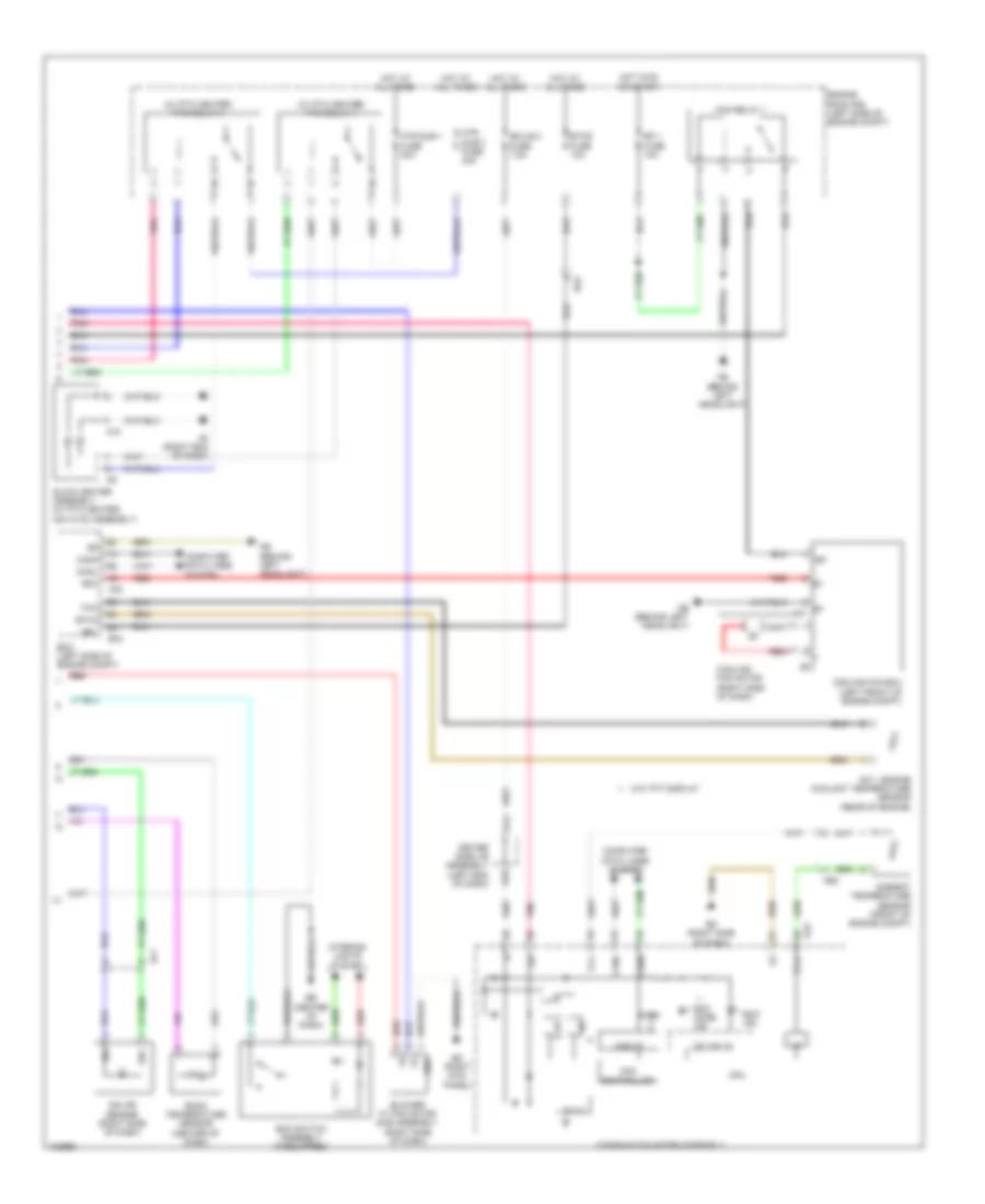
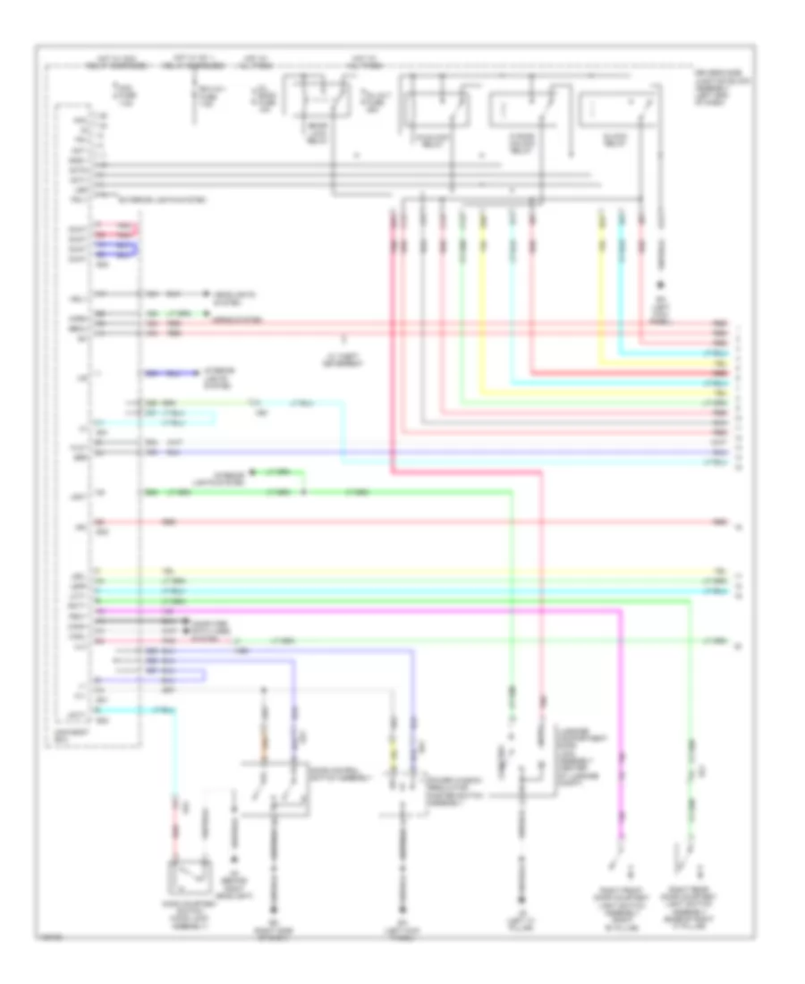
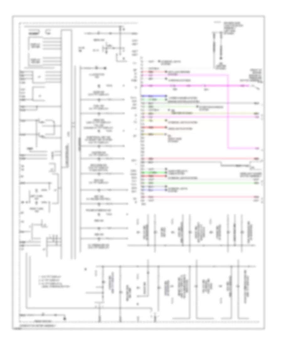
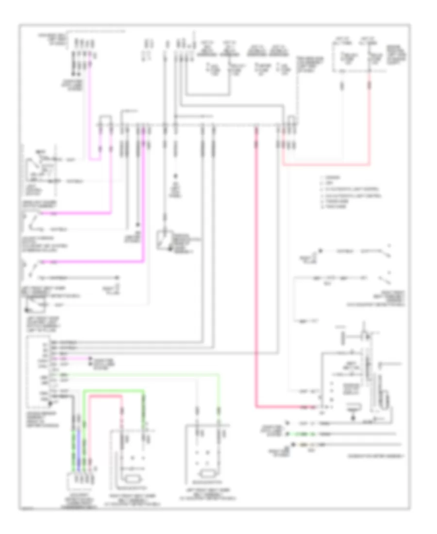
AIR CONDITIONING
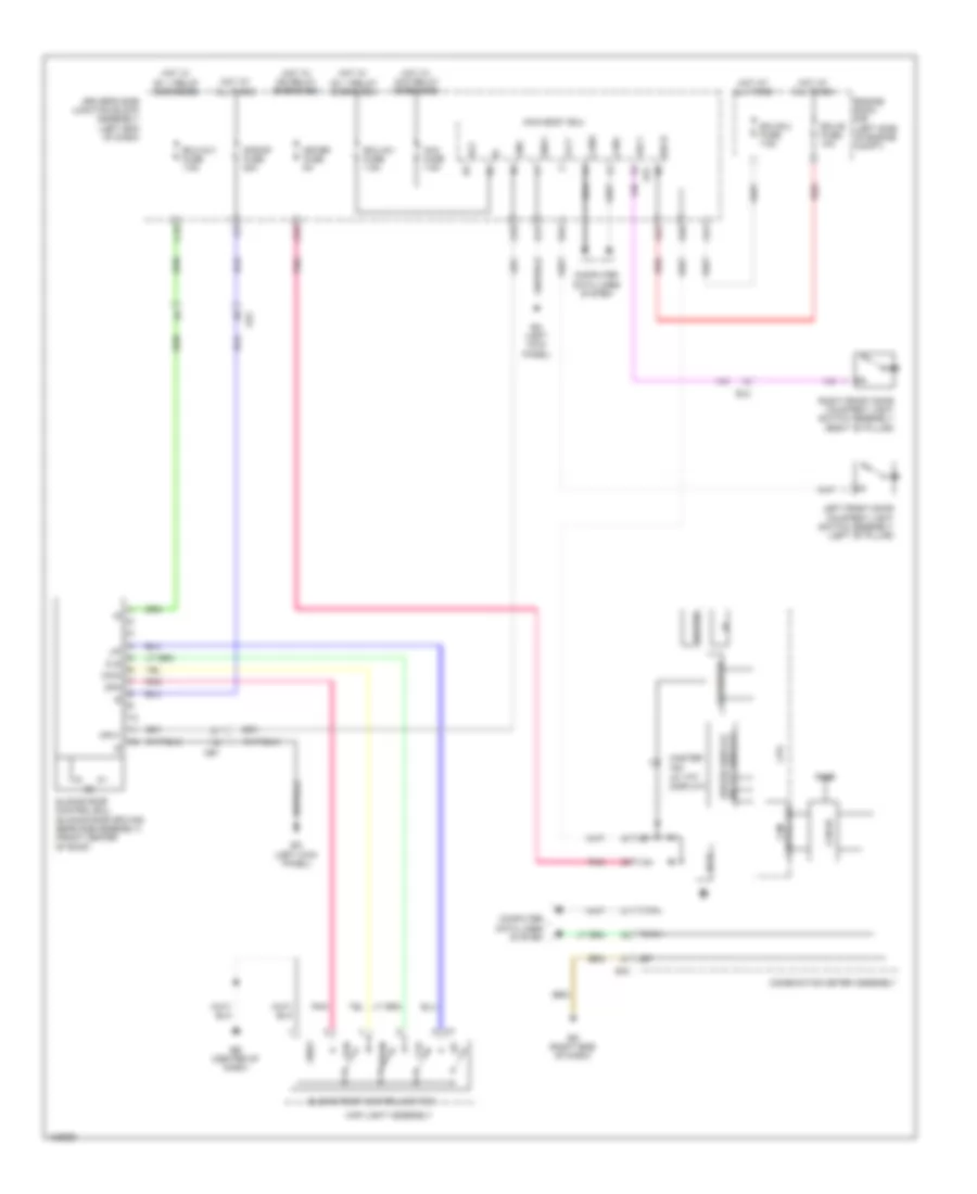
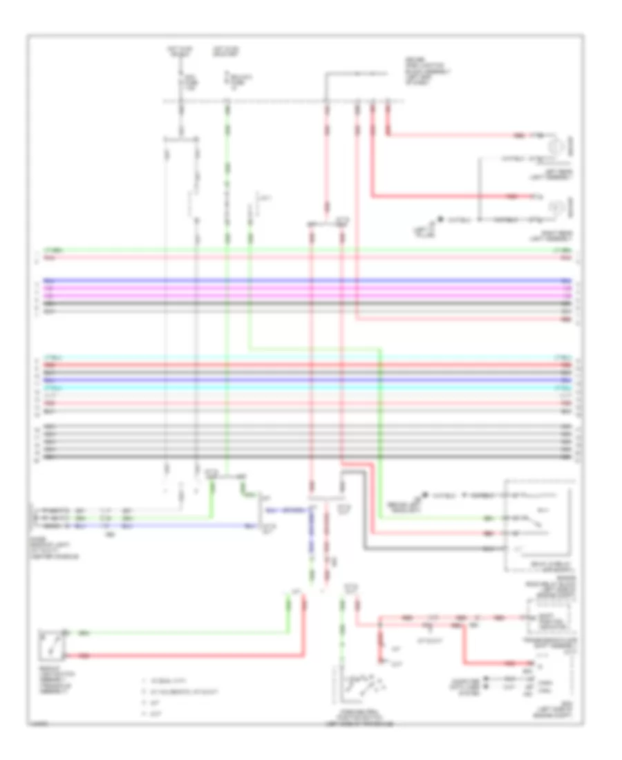
Automatic A/C Wiring Diagram (1 of 2) for Toyota Corolla L 2014

List of elements for Automatic A/C Wiring Diagram (1 of 2) for Toyota Corolla L 2014:
- (right side of dash) ed
- (top of engine) bb
- (w/ valvematic) mgc relay
- A/c amplifier assembly (center of dash)
- A/c blower assembly (a/c harness assembly) (center of dash)
- A/c control assembly
- A/c evaporator temperature sensor
- A/c pressure sensor (right front of
- A23
- A25
- A26
- A44
- A47
- Ae1
- Ae6
- B bus
- B36
- Ba1
- Ba2
- Blw
- Bus
- Bus g
- C55
- Canh
- Canl
- Compressor w/ pulley assembly (left front of engine)
- Computer data lines system
- Connector housing color (black)
- Connector housing color (red)
- D42
- D45
- Damper servo motor (air mix)
- Damper servo motor (fresh/recirculation)
- Damper servo motor (mode control)
- Defogger system
- Driver side j/b assembly (left end of dash)
- E37
- Eb (center of dash)
- Ecos
- Ecu-b2 fuse 7.5a
- Engine compt)
- Engine room r/b (left side of engine compt)
- Gnd
- Hot at all times
- Hot in on or start
- Htr fuse 50a
- Htr-ig fuse 10a
- Ig+
- Ill+
- Ill-
- Interior lights system
- J/c a38
- Lin1
- Lock
- Meter fuse 5a
- Mg+
- Mgc
- Pnk
- Pre
- Ptc1
- Ptc2
- Rdfg
- Rdi fuse 30a
- Rear window defogger switch
- Red
- S5-1
- S5-3
- Sg-1
- Sg-2
- Sga
- Sol+
- Sol-
- Ssr+
- Ssr-
- Tea
- Tsd
- W/ dual vvt-i
- W/ valvematic
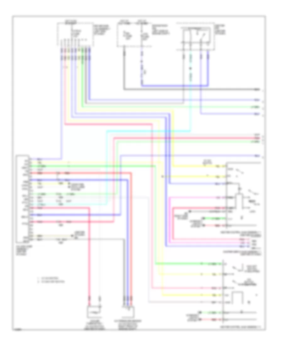
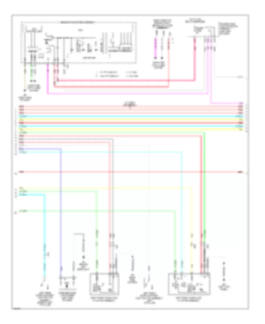
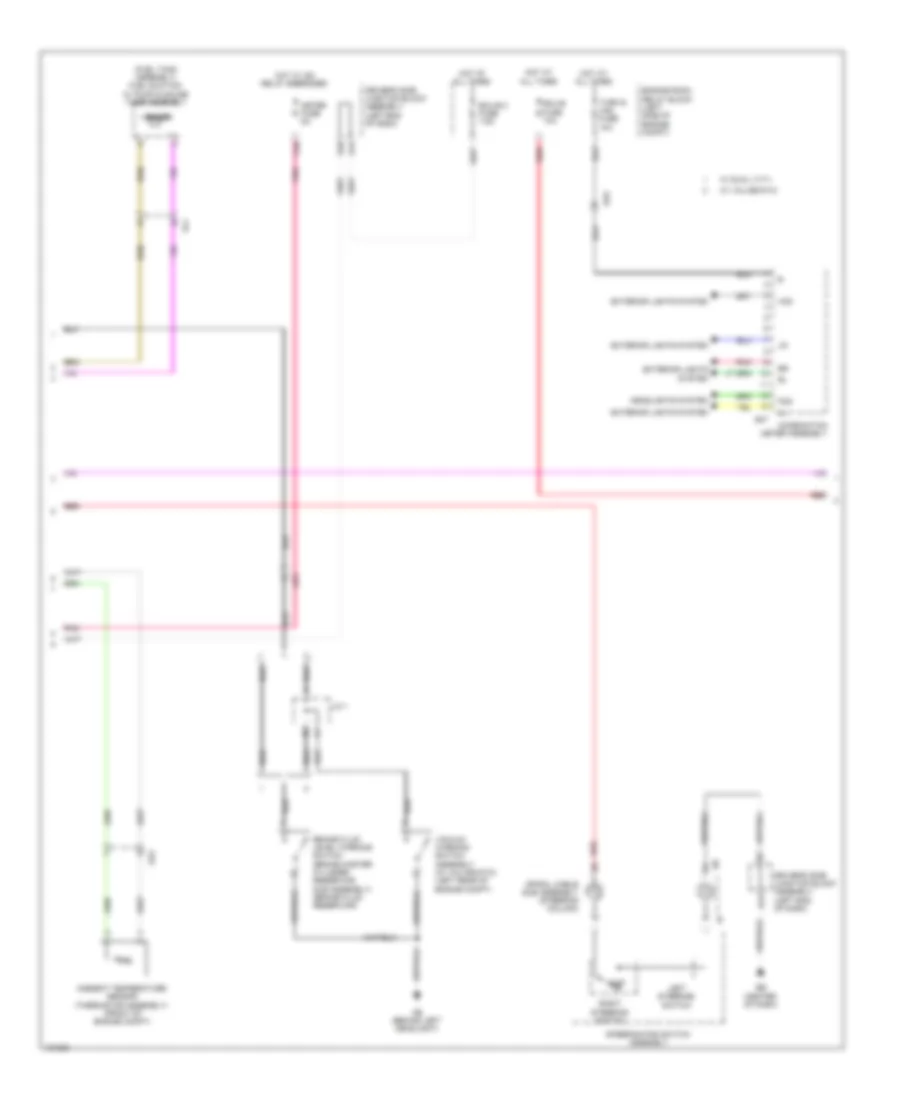
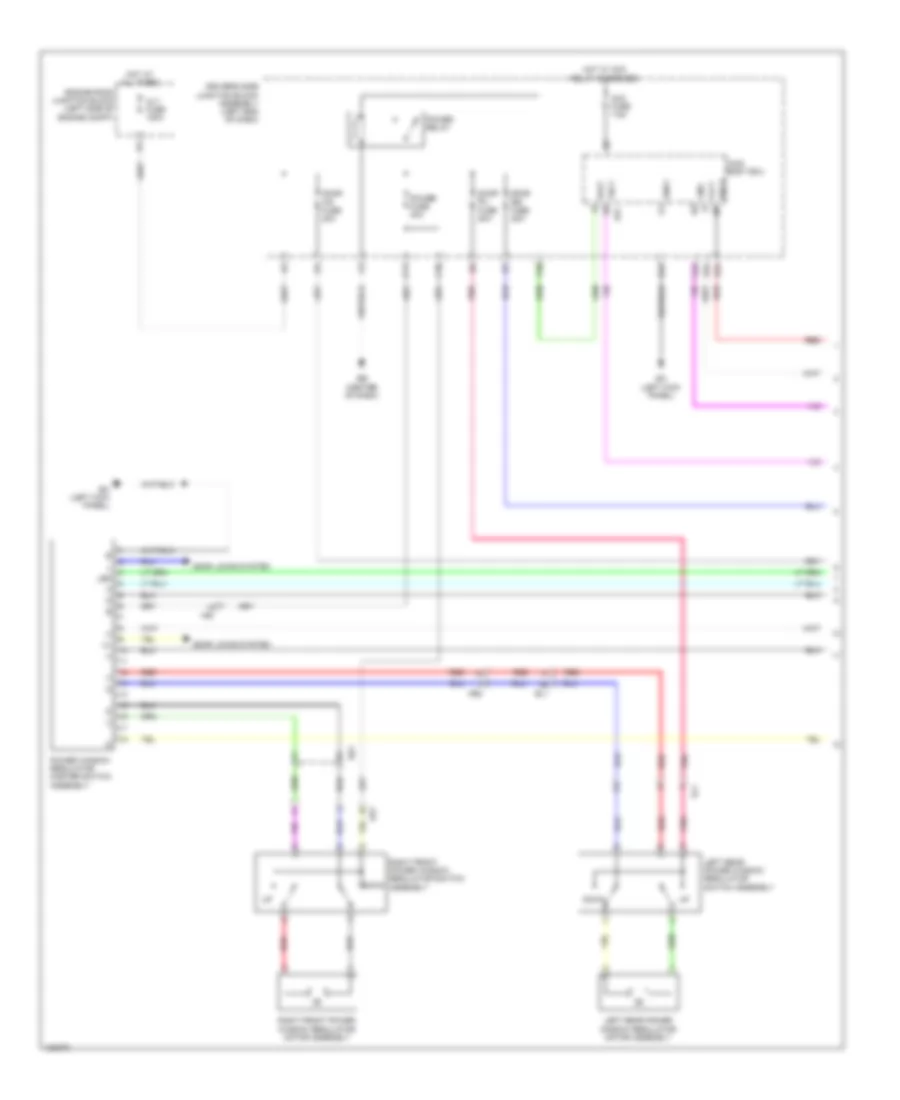
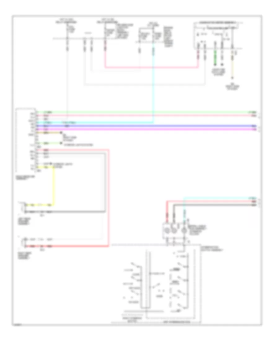
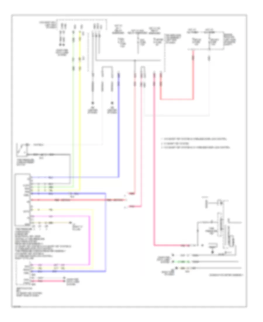
Automatic A/C Wiring Diagram (2 of 2) for Toyota Corolla L 2014
List of elements for Automatic A/C Wiring Diagram (2 of 2) for Toyota Corolla L 2014:
- (w/ ptc heater) ptc relay 1
- (w/ ptc heater) ptc relay 3
- +b1
- +bm
- 5v ic
- 5v+b
- A10
- A40
- A44
- Ab (behind left headlight)
- Ae3
- Af (right end of dash)
- Ambient temperature sensor (front of engine compt)
- B33
- Ba2
- Blower w/ fan motor sub assembly (right side of dash)
- Can controller
- Can i/f
- Canh
- Canl
- Combination meter assembly
- Computer data lines system
- Cooling fan ecu (left front of engine compt)
- Cooling fan motor (right side of dash)
- Cpu
- D40
- Driver side j/b assembly (left end of dash)
- E.f.i. engine coolant temperature sensor (rear of engine)
- E1 a31
- E43
- Eb (center of dash)
- Ec (right kick panel)
- Ecm (left side of engine compt)
- Eco ind
- Eco mode ind
- Eco switch assembly (if equipped)
- Ecu-b 2 fuse 7.5a
- Ed (right side of dash)
- Ef1
- Efi 1 fuse 10a
- Engine room r/b (left side of engine compt)
- Etcs fuse 10a
- Ethw
- Fan relay 1
- Gnd
- Hot at all times
- Hot in on or start
- Htr sub 1 fuse 30a
- Htr sub 3 fuse 30a
- I/f
- Ig+
- Interior lights system
- Led drive
- Pnk
- Quick heater assembly (w/ ptc heater) (on hvac assembly)
- Red
- Rfc
- Room temperature sensor (center of dash)
- Solar sensor (right side of dash)
- Ss+
- Ss-
- Thw
- Tx1+
- Tx1-
- W/o tft display
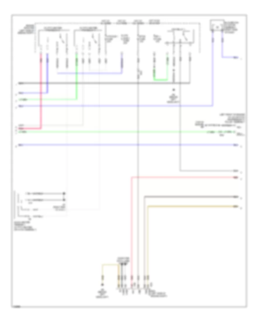
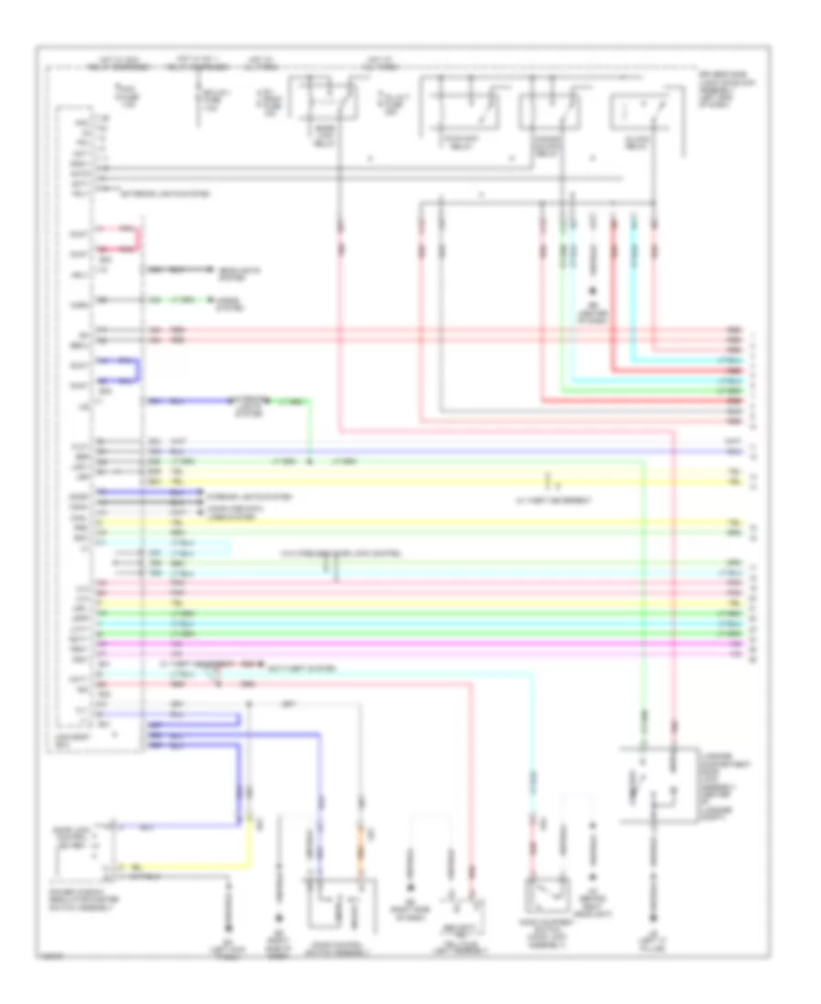
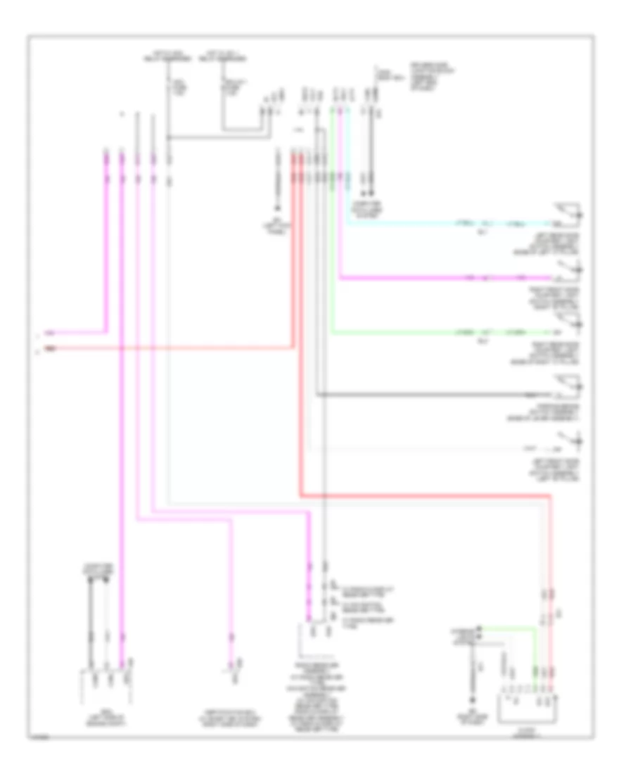
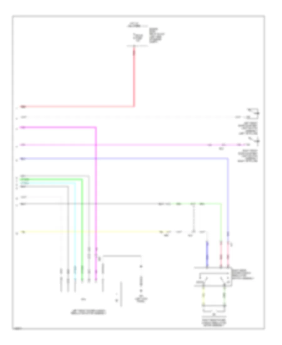
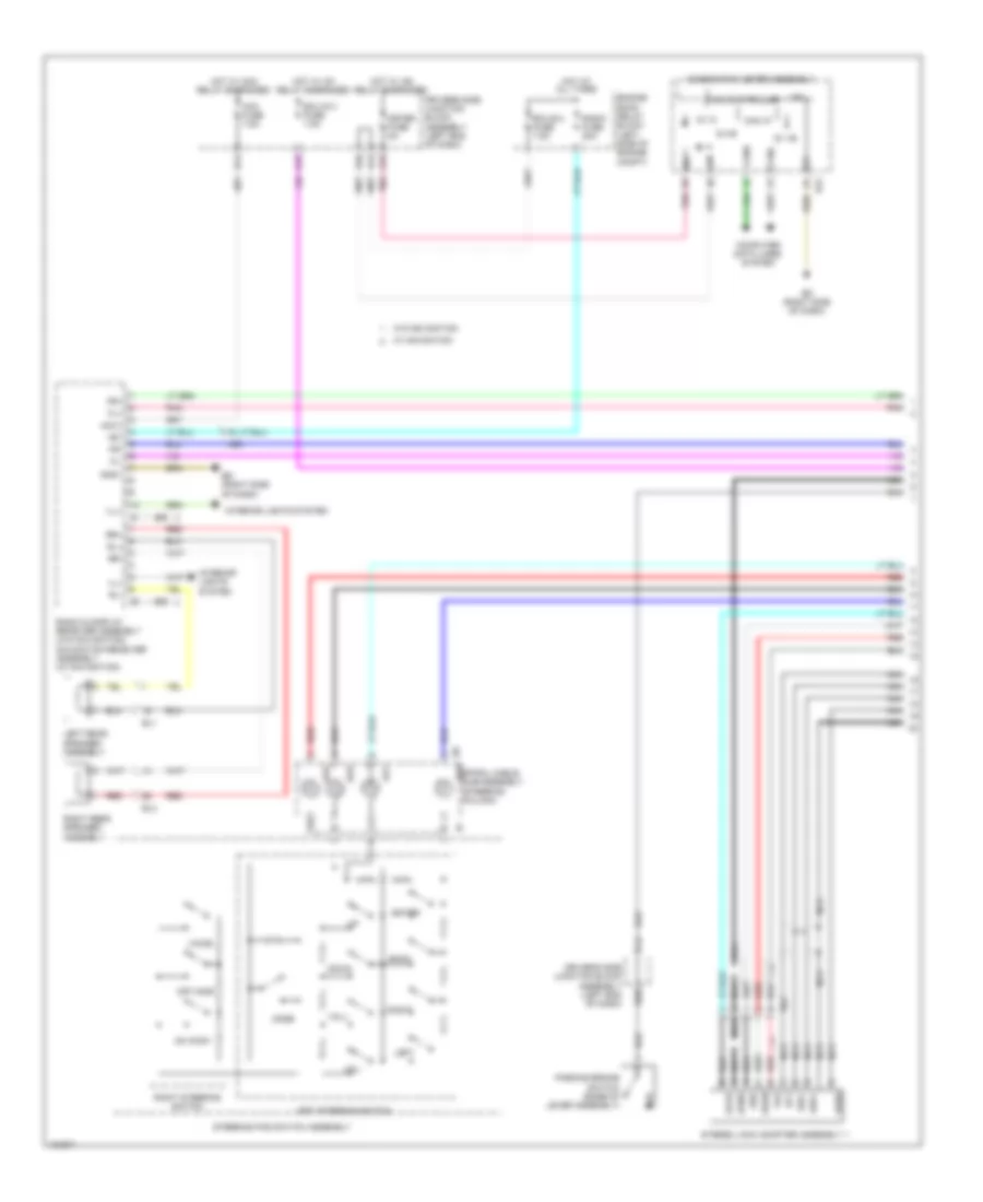
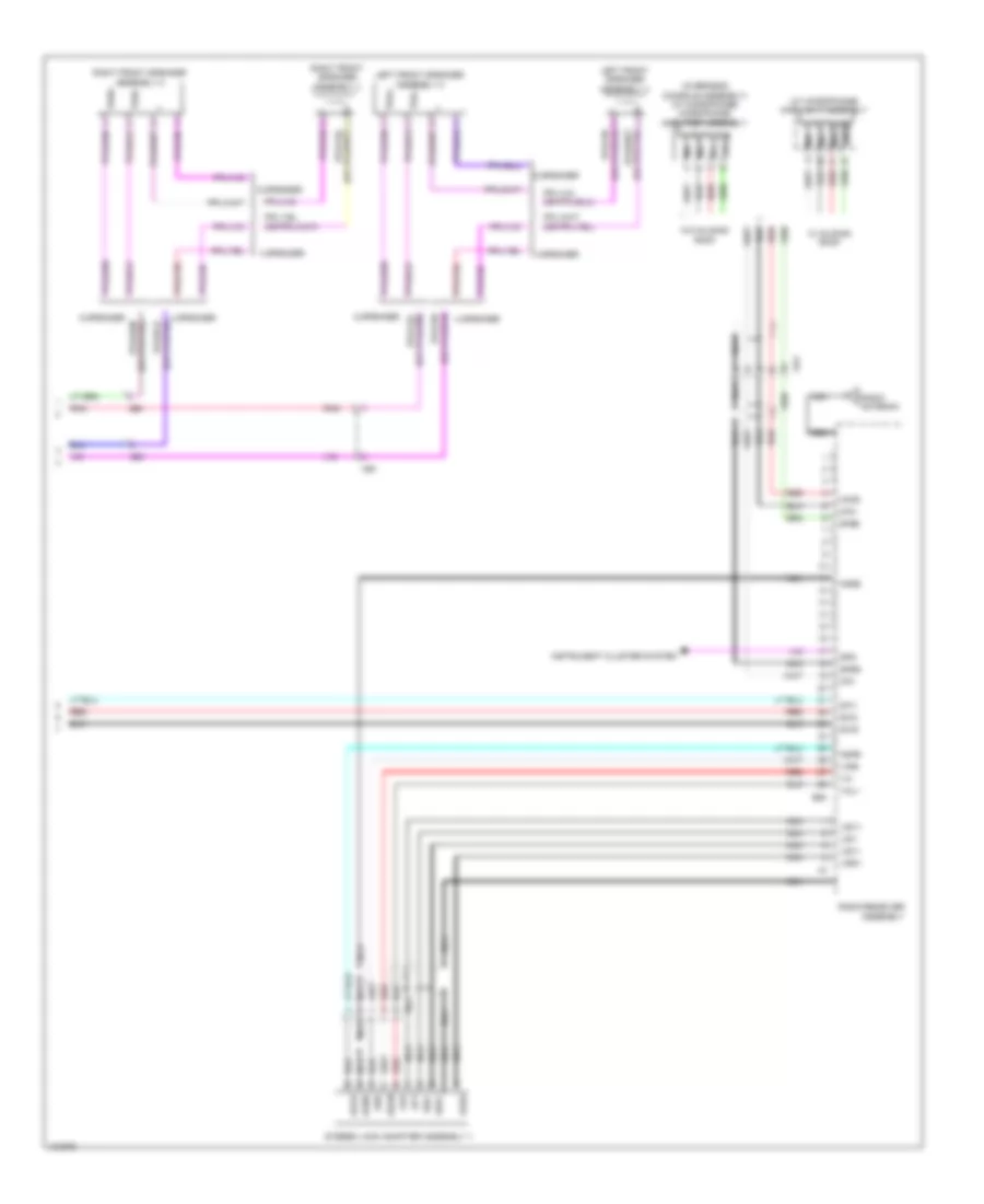
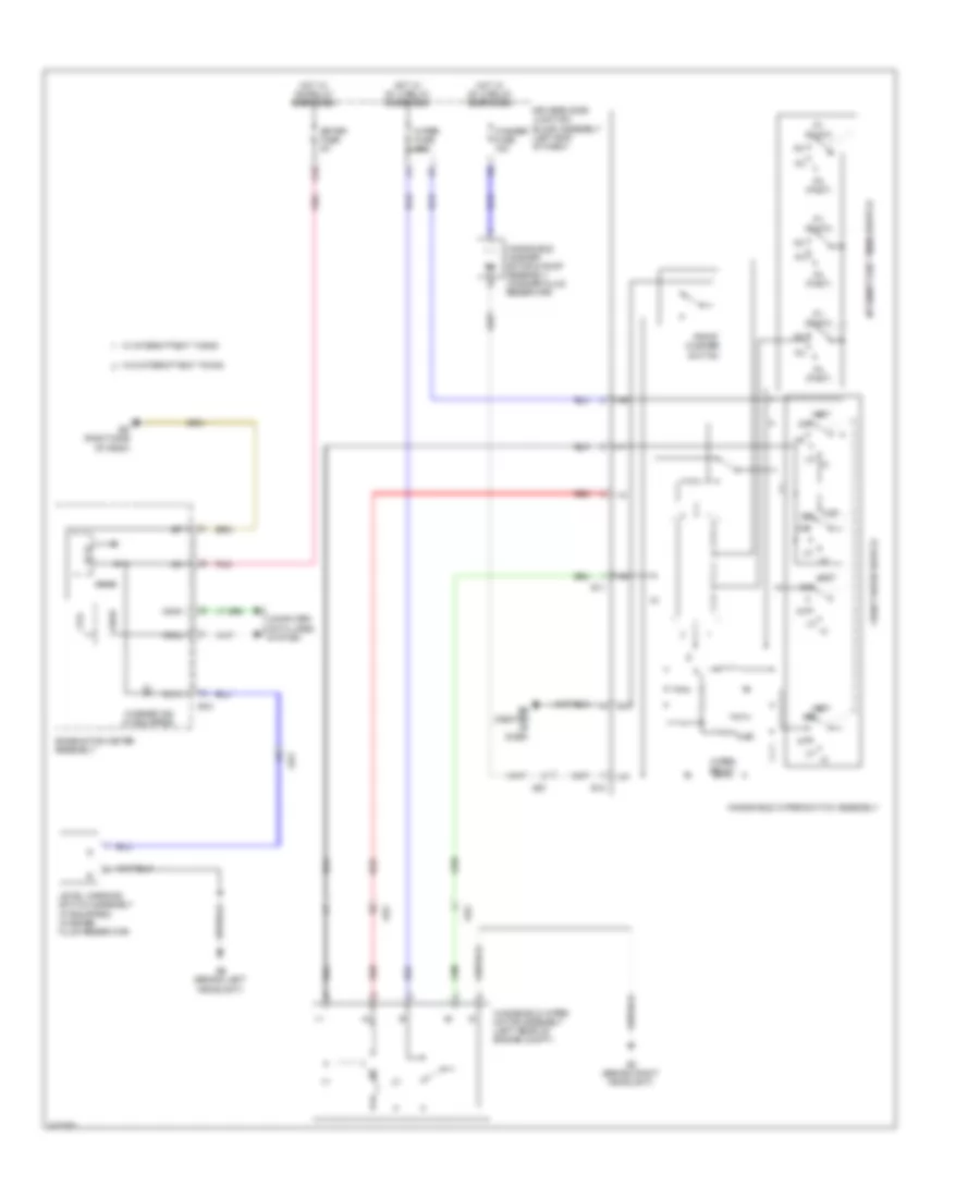
Manual A/C Wiring Diagram (1 of 3) for Toyota Corolla L 2014
List of elements for Manual A/C Wiring Diagram (1 of 3) for Toyota Corolla L 2014:
- (center of dash) eb
- A/c
- A/c amplifier assembly (center of dash)
- A/c pressure sensor (w/ a/c switch) (right front of engine compt)
- A/c switch (if equipped)
- A/c+
- A25
- A26
- Acid
- Ae1
- Ae6
- Aind
- Canh
- Canl
- Center r/b (center of dash)
- Computer data lines system
- Cooler thermistor 1 (w/ a/c switch) (center of dash)
- D23
- D24
- D42
- D43
- D44
- D46
- Damper servo sub assembly 1 (center of dash)
- Driver side j/b assembly (left end of dash)
- Ed (right side of dash)
- Engine room r/b (left side of engine compt)
- F/d
- Free
- Frs
- Gnd
- Heat
- Heater control sub assembly 1 (center of dash)
- Heater control sub assembly 3
- Hot at all times
- Hot in on or start
- Htr fuse 50a
- Htr relay
- Htr-ig fuse 10a
- Ig+
- Ill+
- Ill-
- Interior lights system
- Led
- Led+
- Lock
- Max hot switch (if equipped)
- Pnk
- Pre
- Ptc1
- Ptc2
- Rdi fuse 30a
- Rec
- Red
- S5-3
- Sblw
- Sg-2
- Sg-3
- Sol+
- W/ a/c switch
- W/ max hot switch
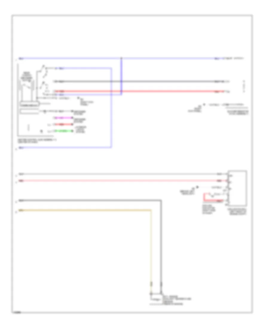
Manual A/C Wiring Diagram (2 of 3) for Toyota Corolla L 2014
List of elements for Manual A/C Wiring Diagram (2 of 3) for Toyota Corolla L 2014:
- (left front of engine) (w/ a/c switch) compressor w/ pulley assembly
- (top of engine) bb
- (w/ ptc heater) ptc relay 1
- (w/ ptc heater) ptc relay 3
- +bm
- A10
- A40
- Ab (behind left headlight)
- Af (right end of dash)
- B33
- Ba2
- Blower fan w/ motor assembly (right side of dash)
- Canh
- Canl
- Computer data lines system
- Ecm (left side of engine compt) ethw
- Efi 1 fuse 10a
- Engine room r/b (left side of engine compt)
- Etcs fuse 10a
- Fan relay 1
- Hot at all times
- Hot in on or start
- Htr sub 1 fuse 30a
- Htr sub 3 fuse 30a
- Pnk
- Quick heater assembly (w/ ptc heater) (on hvac assembly)
- Red
- Rfc
- Sol+
- Sol-
- Thw
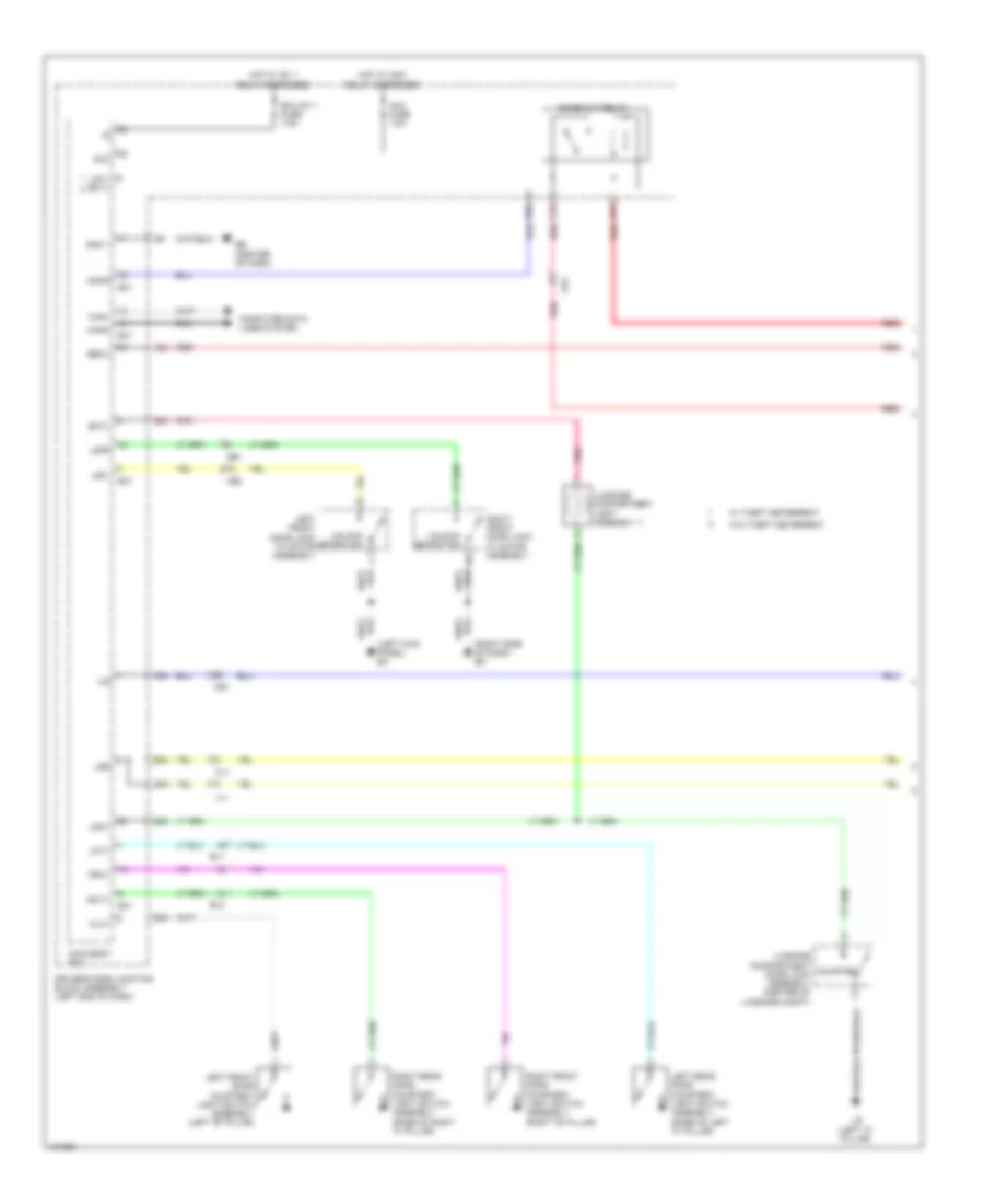
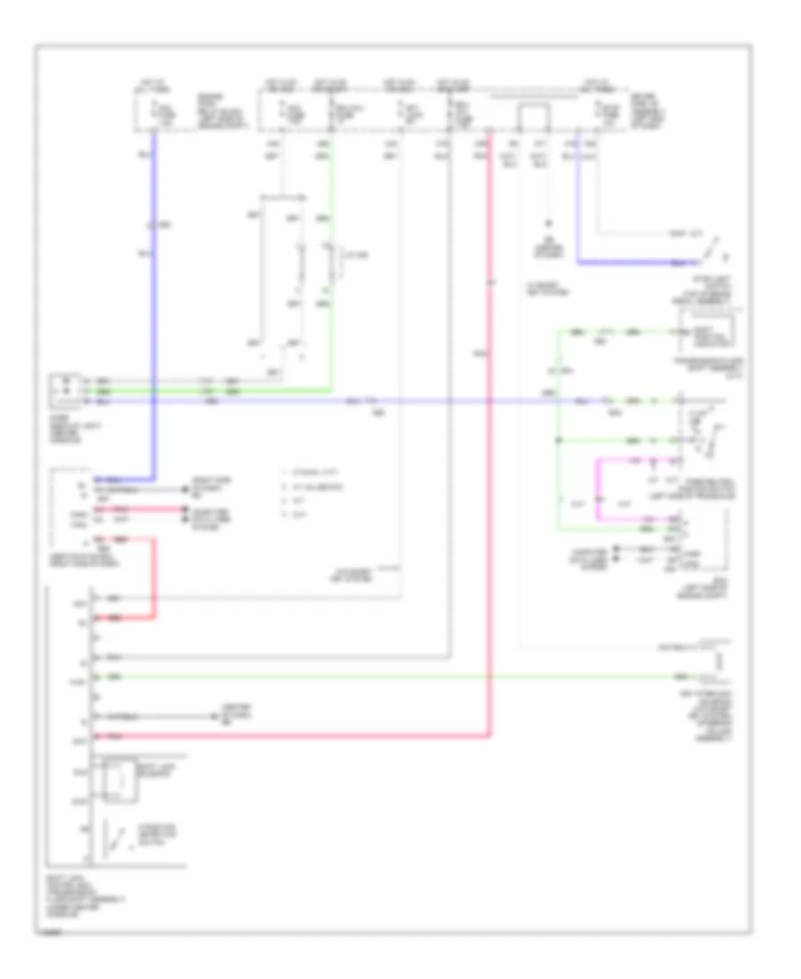
Manual A/C Wiring Diagram (3 of 3) for Toyota Corolla L 2014
List of elements for Manual A/C Wiring Diagram (3 of 3) for Toyota Corolla L 2014:
- +b1
- Ab (behind left headlight)
- Blower resistor (hvac assembly)
- Cooling fan ecu (left front of engine compt)
- Cooling fan motor (right side of dash)
- Defogger system
- E.f.i. engine coolant temperature sensor (rear of engine)
- E1 a31
- Ec (right kick panel)
- Heater control sub assembly 2 (center of dash)
- Ill+
- Ill-
- Interior lights system
- Rear window defogger switch
- Red
- Timer circuit
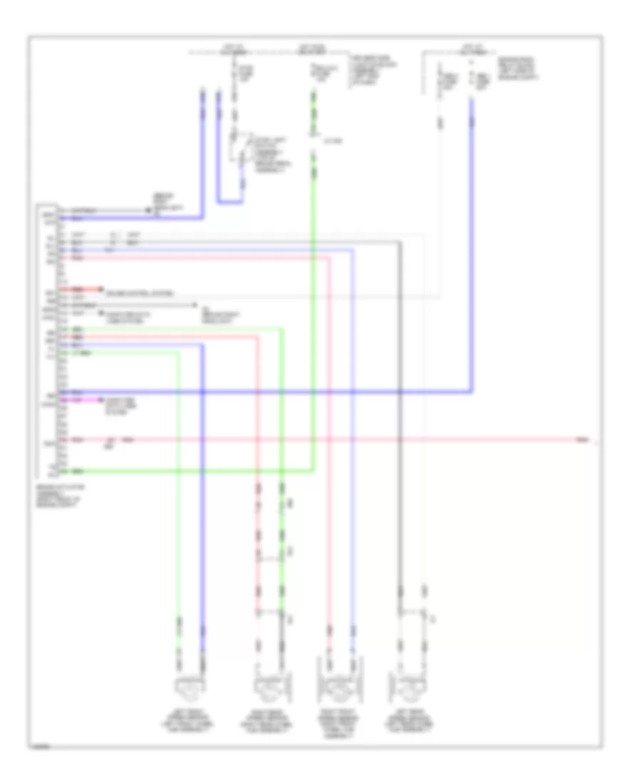
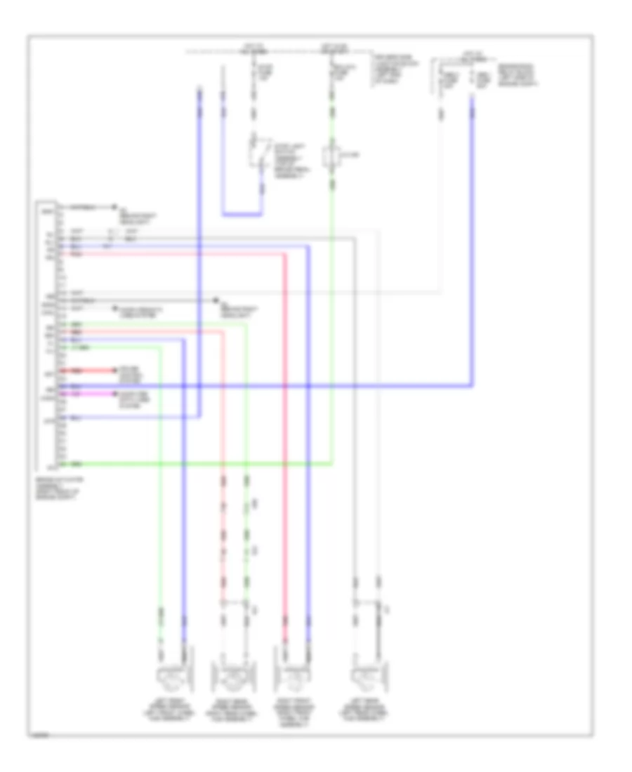
ANTI-LOCK BRAKES
Anti-lock Brakes Wiring Diagram, with VSC (1 of 2) for Toyota Corolla L 2014
List of elements for Anti-lock Brakes Wiring Diagram, with VSC (1 of 2) for Toyota Corolla L 2014:
- (behind right headlight) ac
- +bm
- +bs
- A18
- A19
- A35
- A56
- Abs 1 fuse 50a
- Abs 2 fuse 30a
- Ac (behind right headlight)
- Ae4
- Ae6
- Al1
- Brake actuator assembly (right front of engine compt)
- Canh
- Canl
- Computer data lines system
- Cruise control system
- Csw
- Driver's side junction block assembly (left end of dash)
- Ecu-ig 2 fuse 10a
- El2
- Engine room relay block (left side of engine compt)
- Fl+
- Fl-
- Fr+
- Fr-
- Gnd1
- Gnd2
- Hot at all times
- Hot in on or start
- Ig1
- J/c a38
- Left front speed sensor (left front wheel hub assembly)
- Left rear speed sensor (left rear wheel hub assembly)
- Pnk
- Red
- Right front speed sensor (right front wheel hub assembly)
- Right rear speed sensor (right rear wheel hub assembly)
- Rl+
- Rl-
- Rr+
- Rr-
- Sp1
- Stop fuse 10a
- Stop light switch assembly (top of brake pedal assembly)
- Stp
- Hl1
- Jl1
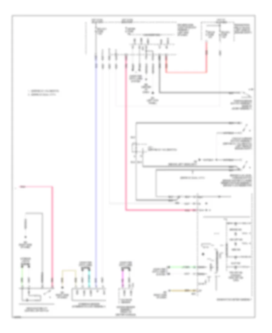
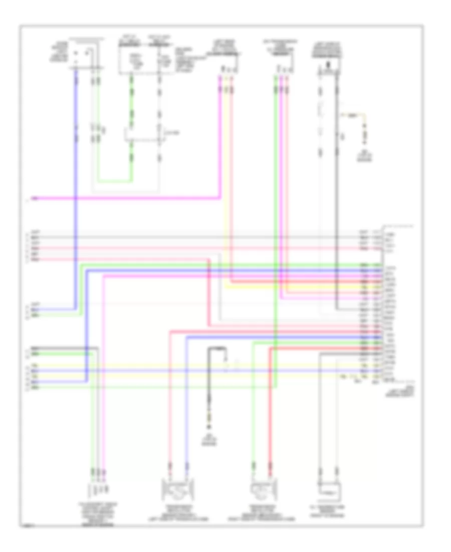
Anti-lock Brakes Wiring Diagram, with VSC (2 of 2) for Toyota Corolla L 2014
List of elements for Anti-lock Brakes Wiring Diagram, with VSC (2 of 2) for Toyota Corolla L 2014:
- 2zr-fae (w/ valvematic)
- 2zr-fe (w/ dual vvt-i)
- 5v ic
- 5v+b
- A24
- A44
- Ab (behind left headlight)
- Abs ind
- Ae3
- Air bag sensor assembly (front of center console)
- Bat
- Becu
- Brake fluid level warning switch (brake master cylinder reservoir sub-assembly) (brake fluid reservoir)
- Brake ind
- C18
- C55
- Can controller
- Can i/f
- Canh
- Canl
- Combination meter assembly
- Computer data lines system
- Cpu
- D12
- D22
- D40
- Driver's side junction block assembly (left end of dash)
- E14
- E30
- E31
- E43
- Ea (left kick panel)
- Eb (center of dash)
- Ecu-b 2 fuse 7.5a
- Ecu-b fuse 10a
- Ecu-ig 3 fuse 7.5a
- Ed (right side of dash)
- Engine room relay block (left side of engine compt)
- Ess
- Gnd1
- Hot at all times
- Hot in on or start
- Ig+
- Interior lights system
- J/c 1 (2zr-fae (w/ valvematic))
- Led driver
- Main body ecu
- Meter fuse 5a
- Parking brake switch assembly (base of lever assembly)
- Pkb
- Pnk
- Red
- Slip ind
- Steering sensor (steering column assembly)
- Trc off ind (canada) trac off ind (usa)
- Vacuum warning switch assembly (2zr-fae (w/ valvematic)) (left rear of engine compt)
- Vehicle stability control off switch
- Vsc off ind
- Yaw rate sensor
Anti-lock Brakes Wiring Diagram, without VSC (1 of 2) for Toyota Corolla L 2014
List of elements for Anti-lock Brakes Wiring Diagram, without VSC (1 of 2) for Toyota Corolla L 2014:
- +bm
- +bs
- A18
- A19
- A35
- A56
- Abs 1 fuse 50a
- Abs 2 fuse 30a
- Ac (behind right headlight)
- Ae6
- Al1
- Brake actuator assembly (right front of engine compt)
- Canh
- Canl
- Computer data lines system
- Cruise control system
- Driver's side junction block assembly (left end of dash)
- Ecu-ig 2 fuse 10a
- El2
- Engine room relay block (left side of engine compt)
- Fl+
- Fl-
- Fr+
- Fr-
- Gnd1
- Gnd2
- Hot at all times
- Hot in on or start
- Ig1
- J/c a38
- Left front speed sensor (left front wheel hub assembly)
- Left rear speed sensor (left rear wheel hub assembly)
- Pnk
- Red
- Right front speed sensor (right front wheel hub assembly)
- Right rear speed sensor (right rear wheel hub assembly)
- Rl+
- Rl-
- Rr+
- Rr-
- Sp1
- Stop fuse 10a
- Stop light switch assembly (top of brake pedal assembly)
- Stp
- Hl1
- Jl1
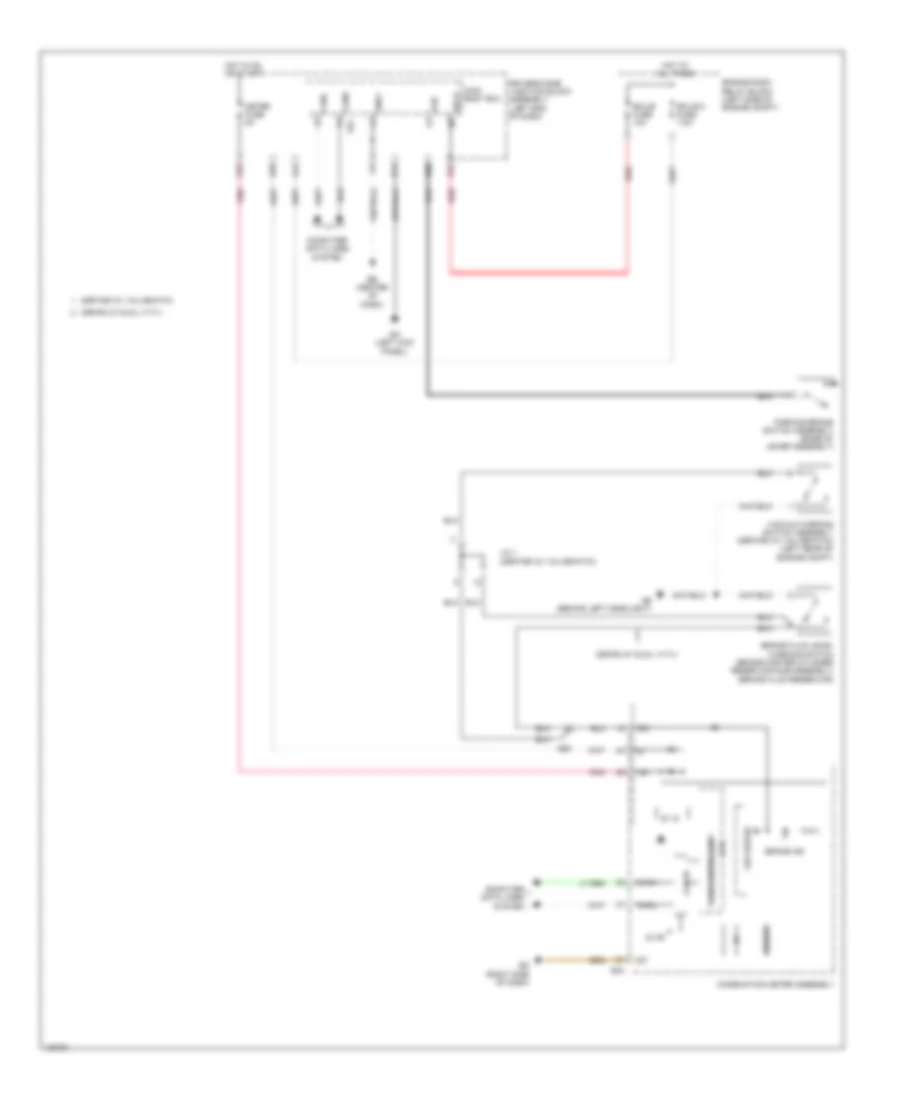
Anti-lock Brakes Wiring Diagram, without VSC (2 of 2) for Toyota Corolla L 2014
List of elements for Anti-lock Brakes Wiring Diagram, without VSC (2 of 2) for Toyota Corolla L 2014:
- 2zr-fae (w/ valvematic)
- 2zr-fe (w/ dual vvt-i)
- 5v ic
- 5v+b
- A24
- A44
- Ab (behind left headlight)
- Ae3
- Becu
- Brake fluid level warning switch (brake master cylinder reservoir sub-assembly) (brake fluid reservoir)
- Brake ind
- Buzzer
- C55
- Can controller
- Can i/f
- Canh
- Canl
- Combination meter assembly
- Computer data lines system
- Cpu
- D12
- D40
- Driver's side junction block assembly (left end of dash)
- E30
- E31
- E43
- Ea (left kick panel)
- Eb (center of dash)
- Ecu-b 2 fuse 7.5a
- Ecu-b fuse 10a
- Ed (right side of dash)
- Engine room relay block (left side of engine compt)
- Gnd1
- Hot at all times
- Hot in on or start
- I/f
- Ig+
- J/c 1 (2zr-fae (w/ valvematic))
- Led driver
- Main body ecu
- Meter fuse 5a
- Parking brake switch assembly (base of lever assembly)
- Pkb
- Pnk
- Red
- Vacuum warning switch assembly (2zr-fae (w/ valvematic)) (left rear of engine compt)
ANTI-THEFT
Forced Entry Wiring Diagram, with Smart Key System (1 of 5) for Toyota Corolla L 2014
List of elements for Forced Entry Wiring Diagram, with Smart Key System (1 of 5) for Toyota Corolla L 2014:
- A24
- A34
- A38
- A53
- A54
- Ac (behind right headlight)
- Acc
- Acc fuse 7.5a
- Act+
- Act-
- Actd
- Ae4
- Becu
- Bk/dr lock relay
- Bzr
- C12
- C13
- C14
- C20
- C21
- C27
- C28
- C29
- C54
- Canh
- Canl
- Computer data lines system
- Courtesy
- D door unlock relay
- D/l back fuse 10a
- D/l-alt fuse 25a
- D/lock relay
- D/unlock relay
- D12
- Door control switch assembly
- Driver's side junction block assembly (left end of dash)
- Dumy
- E24
- E31
- E32
- E34
- E37
- E38
- E39
- Ea (left kick panel)
- Ecu-ig 1 fuse 7.5a
- Ed (right side of dash)
- El2
- Exterior lights system
- Flcy
- Frcy
- Ge1
- Gnd1
- Hcty
- He1
- He2
- Headlights system
- Hood courtesy switch (hood lock assembly)
- Horn
- Horns system
- Hot at all times
- Hot w/ acc relay energized
- Hot w/ ig1 1 relay energized
- Hrly
- Ile
- Ind
- Interior lights system
- Lb (left "c" pillar)
- Lcty
- Lgcy
- Lsfl
- Lsfr
- Lsr
- Luggage compartment door lock assembly (center of luggage compt)
- Main body ecu
- Pnk
- Power window regulator master switch assembly
- Rcty
- Red
- Right front door courtesy light switch assembly (right "b" pillar)
- Right rear door courtesy light switch assembly (base of right "c" pillar)
- Tr+
- Trly
- Ul1
- Ul3
- W/ theft deterrent
Forced Entry Wiring Diagram, with Smart Key System (2 of 5) for Toyota Corolla L 2014
List of elements for Forced Entry Wiring Diagram, with Smart Key System (2 of 5) for Toyota Corolla L 2014:
- (right front of engine compt) brake actuator assembly
- 5v ic
- 5v+b
- A44
- Aa (behind left headlight)
- Ae3
- Buzzer
- C55
- Can controller
- Can i/f
- Canh
- Canl
- Combination meter assembly
- Computer data lines system
- Cpu
- D11
- D28
- D40
- Door ind
- Driver display
- Driver's side junction block assembly (left end of dash)
- E43
- Ea (left kick panel)
- Ed (right side of dash)
- El1
- Electrical key ind
- Ge1
- He1
- He2
- Hot w/ ig2 relay energized
- I/f
- Ig+
- Led driver
- Left front door courtesy light switch assembly (left "b" pillar)
- Left front door lock w/ motor assembly
- Left rear door courtesy light switch assembly (base of left "c" pillar)
- Lock key
- Lssr
- Master ind
- Meter fuse 5a
- Pnk
- Red
- Right front door lock w/ motor assembly
- Sp1
- Tion detec- unlock
- Unlock key
- W/ tft display
- W/ theft deterrent
- W/ vsc
- W/o tft display
- W/o vsc
- Wireless door lock buzzer (left side of dash)
Forced Entry Wiring Diagram, with Smart Key System (3 of 5) for Toyota Corolla L 2014
List of elements for Forced Entry Wiring Diagram, with Smart Key System (3 of 5) for Toyota Corolla L 2014:
- Ante6
- Ante7
- Clgb
- Ecu-b 2 fuse 7.5a
- Ecu-b fuse 10a
- El1
- El2
- Engine room relay block (left side of engine compt)
- Hot at all times
- Indoor electrical key antenna assembly 2 (right side chassis, near b pillar)
- Indoor electrical key antenna assembly 3 (left rear of luggage compt)
- J/c 4 (base of left "c" pillar)
- Jl1
- Kl1
- La (left "b" pillar)
- Lb (left "c" pillar)
- Left rear door lock w/ motor assembly
- Lssr
- Red
- Right rear door lock w/ motor assembly
- S-horn fuse 10a
- S-horn relay (w/ theft deterrent)
- Security horn assembly
- Tion detec- unlock
Forced Entry Wiring Diagram, with Smart Key System (4 of 5) for Toyota Corolla L 2014
List of elements for Forced Entry Wiring Diagram, with Smart Key System (4 of 5) for Toyota Corolla L 2014:
- (left side of engine compt) ecm
- (right "c" pillar) tire pressure warning ecu & receiver (electrical key & tire pressure monitoring system receiver assembly)
- A40
- Ant1
- Ant2
- Ante8
- Canh
- Canl
- Certification ecu (right side of dash)
- Cg6b
- Cg7b
- Cg8b
- Clg6
- Clg7
- Clg8
- Clgb
- Computer data lines system
- Csel
- Data
- E58
- Ed (right side of dash)
- El1
- El2
- Ge2
- Gnd
- Idw
- J/c 4 (base of left c pillar)
- La (left "b" pillar)
- Lb (left "c" pillar)
- Lc (right "c" pillar)
- Luggage electrical key switch (top center of trunk lid)
- Neo
- Pnk
- Rco
- Rdam
- Rear electrical key antenna (rear bumper assembly)
- Red
- Right front door outside handle assembly
- Sens
- Smart door control receiver assembly
- Trg+
- Tsw5
- W/ tire pressure warning system
- W/o tire pressure warning system
Forced Entry Wiring Diagram, with Smart Key System (5 of 5) for Toyota Corolla L 2014
List of elements for Forced Entry Wiring Diagram, with Smart Key System (5 of 5) for Toyota Corolla L 2014:
- (right side chassis, near "b" pillar) indoor electrical key antenna assembly 1
- A19
- A24
- A35
- Accd
- Ae2
- Ae3
- Agnd
- Am2 fuse 7.5a
- Ant1
- Ant2
- Ante5
- Antenna coil
- Canh
- Canl
- Certification ecu (right side of dash)
- Cg1b
- Cg2b
- Cg5b
- Clg1
- Clg2
- Clg5
- Clgb
- Code
- Computer data lines system
- Cutb
- D39
- Driver's side junction block assembly (left end of dash)
- Dumy
- E57
- E59
- Ea (left kick panel)
- Ecu-b fuse 10a
- Ed (right side of dash)
- El2
- Engine room relay block (left side of engine compt)
- Engine switch
- Gnd
- He2
- Hot at all times
- Hot w/ ig2 relay energized
- Ig1d
- Ig2d
- Ign fuse 7.5a
- Ill-
- Ind
- Left front door outside handle assembly
- Lin
- Pnk
- Pos1
- Pos2
- Power distribution system
- Red
- Security ind
- Sen1
- Sen2
- Sens
- Shift interlock system
- Slp
- Slr+
- Spd
- Ss1
- Ss2
- Ssw1
- Ssw2
- Sta
- Star
- Starting/charging system
- Stop fuse 10a
- Stop light switch assembly (top of brake pedal assembly)
- Stp1
- Swil
- Telltale light assembly
- Trg+
- Tsw1
- Tsw2
- Txct
- Vc5
Forced Entry Wiring Diagram, without Smart Key System (1 of 3) for Toyota Corolla L 2014
List of elements for Forced Entry Wiring Diagram, without Smart Key System (1 of 3) for Toyota Corolla L 2014:
- A24
- A34
- A38
- A53
- A54
- Ac (behind right headlight)
- Acc
- Acc fuse 7.5a
- Act+
- Act-
- Actd
- Ae4
- Anti-theft system
- Becu
- Bk/dr lock relay
- Bzr
- C12
- C13
- C14
- C20
- C21
- C22
- C27
- C28
- C29
- C54
- Canh
- Canl
- Computer data lines system
- Courtesy
- D door unlock relay
- D/l back fuse 10a
- D/l-alt fuse 25a
- D/lock relay
- D/unlock relay
- Domr
- Door control switch assembly
- Door lock control switch
- Driver's side junction block assembly (left end of dash)
- Dumy
- E24
- E31
- E32
- E34
- E37
- E38
- E39
- Ea (left kick panel)
- Eb (center of dash)
- Ecu-ig 1 fuse 7.5a
- Ed (right side of dash)
- Exterior lights system
- Flcy
- Frcy
- Ge1
- Gnd1
- Hcty
- He1
- Headlights system
- Hood courtesy switch (hood lock assembly)
- Horn
- Horns system
- Hot at all times
- Hot w/ acc relay energized
- Hot w/ ig1 1 relay energized
- Hrly
- Ile
- Ill-
- Ind
- Interior lights system
- Ksw
- Lb (left "c" pillar)
- Lcty
- Lgcy
- Lock
- Lsfl
- Lsfr
- Lsr
- Luggage compartment door lock assembly (center of luggage compt)
- Main body ecu
- Pnk
- Power window regulator master switch assembly
- Prg
- Rcty
- Rda
- Red
- Security ind
- Telltale light assembly
- Tr+
- Trly
- Ul1
- Ul2
- Ul3
- Unlock
- W/ theft deterrent
- W/o wireless door lock control
Forced Entry Wiring Diagram, without Smart Key System (2 of 3) for Toyota Corolla L 2014
List of elements for Forced Entry Wiring Diagram, without Smart Key System (2 of 3) for Toyota Corolla L 2014:
- 5v ic
- 5v+b
- A44
- Buzzer
- C30
- C32
- C55
- Can controller
- Can i/f
- Canh
- Canl
- Combination meter assembly
- Computer data lines system
- Cpu
- D17
- D40
- Detection unlock
- Door ind (w/o tft display)
- Driver display
- Driver's side junction block assembly (left end of dash)
- E43
- Ea (left kick panel)
- Eb (center of dash)
- Ecu-b 2 fuse 7.5a
- Ed (right side of dash)
- El1
- El2
- Engine room relay block (left side of engine compt)
- Ge1
- He1
- He2
- Hot at all times
- Hot w/ ig2 relay energized
- I/f
- Ig+
- Key lock
- Key un- lock
- Led driver
- Left front door lock w/ motor assembly
- Left rear door courtesy light switch assembly (base of left "c" pillar)
- Lock
- Lock key
- Lssr
- Meter fuse 5a
- Pnk
- Red
- Right front door courtesy light switch assembly (right "b" pillar)
- Right front door lock w/ motor assembly
- Right rear door courtesy light switch assembly (base of right "c" pillar)
- Un- key
- Un-lock warning switch (steering column)
- W/ theft deterrent
- W/ wireless door lock control
- W/o wireless door lock control
Forced Entry Wiring Diagram, without Smart Key System (3 of 3) for Toyota Corolla L 2014
List of elements for Forced Entry Wiring Diagram, without Smart Key System (3 of 3) for Toyota Corolla L 2014:
- (left "c" pillar) door control receiver
- (left end of dash) driver's side junction block assembly
- (right "c" pillar) tire pressure warning ecu & receiver (door control & tire pressure monitoring system receiver assembly)
- A24
- Aa (behind left headlight)
- Detection unlock
- E31
- Ecu-b fuse 10a
- El1
- Engine room relay block (left side of engine compt)
- Gnd
- Hot at all times
- J/c 4 (base of left "c" pillar)
- Jl1
- Kl1
- Lb (left "c" pillar)
- Lc (right "c" pillar)
- Left front door courtesy light switch assembly (left "b" pillar)
- Left rear door lock w/ motor assembly
- Lssr
- Prg
- Rda
- Red
- Right rear door lock w/ motor assembly
- S-horn fuse 10a
- S-horn relay (w/ theft deterrent)
- Security horn assembly
- W/ theft deterrent
- W/ tire pressure warning system
- W/o tire pressure warning system
- Wireless door lock buzzer (left side of dash)
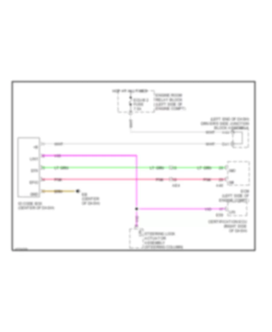
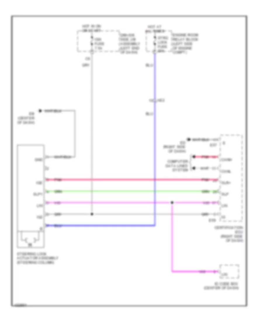
Immobilizer Wiring Diagram, with Smart Key System for Toyota Corolla L 2014
List of elements for Immobilizer Wiring Diagram, with Smart Key System for Toyota Corolla L 2014:
- (left end of dash) driver's side junction block assembly
- A40
- A44
- Ae4
- Certification ecu (right side of dash)
- D41
- E59
- Eb (center of dash)
- Ecm (left side of engine compt)
- Ecu-b 2 fuse 7.5a
- Efii
- Efio
- Engine room relay block (left side of engine compt)
- Gnd
- Hot at all times
- Id code box (center of dash)
- Imi
- Imo
- Lin
- Lin1
- Pnk
- Steering lock actuator assembly (steering column)
Immobilizer Wiring Diagram, without Smart Key System for Toyota Corolla L 2014
List of elements for Immobilizer Wiring Diagram, without Smart Key System for Toyota Corolla L 2014:
- A40
- A44
- Ae4
- Ant1
- Ant2
- C30
- C31
- C44
- Computer data lines system
- D17
- D41
- Driver's side junction block assembly (left end of dash)
- E32
- Eb (center of dash)
- Ecm (left side of engine compt)
- Ecu-b 2 fuse 7.5a
- Ed (right side of dash)
- Efii
- Efio
- Engine room relay block (left side of engine compt)
- Gnd
- Hot at all times
- Hot w/ ig2 relay energized
- Ign fuse 7.5a
- Ill-
- Imi
- Imo
- Ind
- Ksw
- Main body ecu (left end of dash)
- Pnk
- Red
- Security indicator
- Telltale light assembly
- Transponder key coil
- Transponder key ecu assembly (center of dash)
- Un-lock warning switch (steering column)
- W/ theft deterrent
BODY CONTROL MODULES
Body Control Modules Wiring Diagram (1 of 2) for Toyota Corolla L 2014
List of elements for Body Control Modules Wiring Diagram (1 of 2) for Toyota Corolla L 2014:
- (left end of dash)
- A24
- A28
- A34
- A38
- A49
- A50
- A53
- A54
- Acc
- Acc fuse 7.5a
- Act+
- Act-
- Actd
- Bctl
- Becu
- Bzr
- C41
- C42
- C43
- C49
- C52
- C53
- C54
- Canh
- Canl
- Cltb
- Clte
- Clts
- D12
- Dbkl
- Dim
- Dome cut relay
- Domr
- Door locks & anti- theft systems
- Door locks & anti-theft systems
- Door locks system
- Driver's side junction block assembly
- Drl
- E24
- E25
- E30
- E31
- E32
- E34
- E38
- E39
- E40
- Ea (left kick panel)
- Eb (center of dash)
- Ecu- ig 1 fuse 7.5a
- Ecu-b fuse 10a
- Engine room relay block (left side of engine compt)
- Exterior lights & interior lights systems
- Ffgo
- Ffog
- Flcy
- Frcy
- Gnd1
- Head
- Headlights system
- Headlights, exterior lights & interior lights systems
- Horn
- Horns system
- Hot at all times
- Hot w/ acc relay energized
- Hot w/ ig1 1 relay energized
- Hrly
- Ile
- Instrument cluster & headlights systems
- Interior lights system
- Koff
- Ksw
- Lcty
- Lgcy
- Lgyl bcyl
- Lin2
- Lsfl
- Lsfr
- Lsr
- Main body ecu (left end of dash)
- Navigation & sound systems
- Pkb
- Pnk
- Power tops system
- Power windows system
- Prg
- Rcty
- Rda
- Red
- Tail
- Tr+
- Trly
- Trunk, tailgate, fuel doors system
- Ul1
- Ul2
- Ul3
- W/ theft deterrent
- W/o theft deterrent
- Warning systems
Body Control Modules Wiring Diagram (2 of 2) for Toyota Corolla L 2014
List of elements for Body Control Modules Wiring Diagram (2 of 2) for Toyota Corolla L 2014:
- (left side of engine compt)
- (right end of dash) can junction connector 2
- (right front of engine compt) brake actuator assembly
- A/c amplifier assembly (center of dash)
- A40
- Ae4
- Air bag sensor assembly (front of center console)
- Anti-theft system
- Automatic a/c
- Can junction connector 3 (center of dash)
- Canh
- Canl
- Certification ecu (w/ smart key system) (right side of dash)
- Combination meter assembly
- Data link connector 3 (left side of dash)
- Dumy
- E14
- E29
- E32
- E37
- E40
- E43
- E59
- Ecm
- Hcty
- Ind
- Interior lights system
- Main body ecu (left end of dash)
- Manual a/c
- Pnk
- Power steering ecu assembly (behind instrument cluster)
- Radio & display receiver assembly (w/ radio & display receiver type) navigation receiver assembly (w/ navigation receiver type) e67
- Red
- Steering sensor (w/ vsc) (steering column assembly)
- W/ navigation receiver type
- W/ radio & display receiver type
COMPUTER DATA LINES
Computer Data Lines Wiring Diagram (1 of 2) for Toyota Corolla L 2014
List of elements for Computer Data Lines Wiring Diagram (1 of 2) for Toyota Corolla L 2014:
- (behind instrument cluster) power steering ecu assembly
- (right "c" pillar) lc
- Ae4
- Air bag sensor assembly (front of center console)
- Ba1
- Bat
- Bb (top of engine)
- Can j/c 3 (center of dash)
- Canh
- Canl
- Certification ecu (right side of dash)
- Combination meter assembly
- D17
- D20
- D21
- Data link connector 3 (left side of dash)
- Driver's side j/b assembly (left end of dash)
- E14
- E29
- E40
- E43
- E59
- E67
- Eb (center of dash)
- El2
- Hot at all times
- Id code box (center of dash)
- Limit switch
- Lin
- Lin1
- Ls+
- Ls-
- Ls2
- Navigation receiver assembly (w/ navigation) radio & display receiver assembly (w/o navigation)
- Obd fuse 7.5a
- Op4
- Pnk
- Red
- Right front seat inner belt assembly
- Sil
- Steering lock actuator assembly (steering column)
- Tac
- Tmmc made w/ occupant detection ecu
- Tmmms made w/ occupant detection ecu
- W/ navigation
- W/o navigation
Computer Data Lines Wiring Diagram (2 of 2) for Toyota Corolla L 2014
List of elements for Computer Data Lines Wiring Diagram (2 of 2) for Toyota Corolla L 2014:
- (center of dash) transponder key ecu assembly
- (left end of dash) (w/ valvematic) can j/c 1
- (left front of engine compt) generator control ecu assembly
- (left side of engine compt) ecm
- (rear of engine) continuously variable valve lift controller assembly
- (right end of dash) can j/c 2
- (under front passenger's seat) occupant detection ecu
- A/c amplifier (center of dash)
- A/c control assembly
- A35
- A36
- A37
- A40
- Ae4
- Automatic a/c
- B33
- B37
- Ba1
- Ba2
- Brake actuator assembly (right front of engine compt)
- C52
- C53
- Ca3n
- Ca3p
- Can+
- Can-
- Canh
- Canl
- Dia
- Driver's side j/b assembly (left end of dash)
- E31
- E37
- El2
- Generator (w/ regulator assembly)
- He1
- Left front power window regulator motor assembly
- Lin
- Lin1
- Lin2
- Ls2
- Main body ecu
- Manual a/c
- Mpx1
- Oe1
- Pnk
- Red
- Sliding roof control ecu (sliding roof drive gear sub-assembly)
- Steering sensor (w/ vsc) (steering column assembly)
- Tach
- W/ occupant detection ecu
- W/ smart key system
- W/o occupant detection ecu
- W/o smart key system
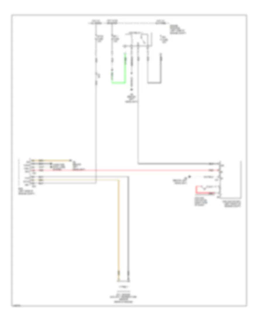
COOLING FAN
Cooling Fan Wiring Diagram for Toyota Corolla L 2014
List of elements for Cooling Fan Wiring Diagram for Toyota Corolla L 2014:
- +b1
- +bm
- A40
- Ab (behind left headlight)
- B33
- Ba2
- Canh
- Canl
- Computer data lines system
- Cooling fan ecu (left front of engine compt)
- Cooling fan motor (right side of dash)
- E.f.i. engine coolant temperature sensor (rear of engine)
- E1 a31
- Ecm (left side of engine compt)
- Efi 1 fuse 10a
- Engine room r/b (left side of engine compt)
- Etcs fuse 10a
- Ethw
- Fan relay 1
- Hot at all times
- Hot in on or start
- Rdi fuse 30a
- Red
- Rfc
- Thw
CRUISE CONTROL
Cruise Control Wiring Diagram (1 of 2) for Toyota Corolla L 2014
List of elements for Cruise Control Wiring Diagram (1 of 2) for Toyota Corolla L 2014:
- (center console)
- +res
- -set
- A/t
- A40
- A56
- Ab (behind left headlight)
- Accelerator pedal sensor assembly (base of accelerator pedal)
- Ae2
- Ae3
- Ae4
- B33
- Ba (top of engine)
- Ba1
- Ba2
- Batt
- Cancel
- Canh
- Canl
- Ccs
- Computer data lines system
- Cruise control main switch
- Cruise control switch
- Cruise control switch wire
- Cvt
- Diode (back-up light)
- Driver's side j/b assembly (left end of dash)
- Ecc
- Ecm (left side of engine compt)
- Ecu- ig 2 fuse 10a
- Efi 1 fuse 10a
- Efi main fuse 20a
- Efi main relay
- Engine room r/b (left side of engine compt)
- Epa
- Epa2
- Eta
- Ge01
- Hot at all times
- Hot in on or start
- Igsw
- J/c a38
- Mrel
- On-off
- Park/neutral position switch (left side of transaxle)
- Pnk
- Red
- Shift position indicator
- Spd
- Spiral cable sub-assembly (steering column)
- St1-
- Stp
- Throttle body assembly (air intake manifold opening)
- Transmission floor shift assembly
- Vcp2
- Vcpa
- Vcta
- Vpa
- Vpa2
- Vta
- Vta1
- Vta2
Cruise Control Wiring Diagram (2 of 2) for Toyota Corolla L 2014
List of elements for Cruise Control Wiring Diagram (2 of 2) for Toyota Corolla L 2014:
- +bs
- 5v +b
- 5v ic
- A18
- A19
- A35
- A36
- A37
- A40
- A44
- A48
- Abs 2 fuse 30a
- Ac (behind right headlight)
- Ae3
- Ae6
- Al1
- Brake actuator assembly (right front of engine compt)
- C55
- Can i/f
- Canh
- Canl
- Chk
- Combination meter assembly
- Computer data lines system
- Cpu
- Cruise ind
- D28
- D40
- Driver display
- Driver's side junction block assembly (left end of dash)
- E43
- Ecu-b fuse 7.5a
- Ed (right side of dash)
- El2
- Engine room relay block (left side of engine compt)
- Fl+
- Fl-
- Fr+
- Fr-
- Gnd1
- Gnd2
- Hot at all times
- Hot in on or start
- I/f
- Ig+
- Ign fuse 7.5a
- Led driver
- Left front speed sensor (left front wheel hub assembly)
- Left rear speed sensor (left rear wheel hub assembly)
- Malfunction ind lamp
- Meter fuse 5a
- Pnk
- Red
- Right front speed sensor (right front wheel hub assembly)
- Right rear speed sensor (right rear wheel hub assembly)
- Rl+
- Rl-
- Rr+
- Rr-
- Set ind
- Sp1
- Stop fuse 10a
- Stop light switch (top of brake pedal assembly)
- Stp
- W/ vsc
- W/o vsc
- Hl1
- Jl1
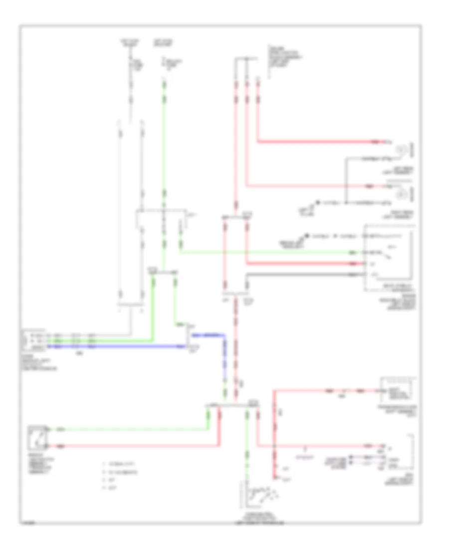
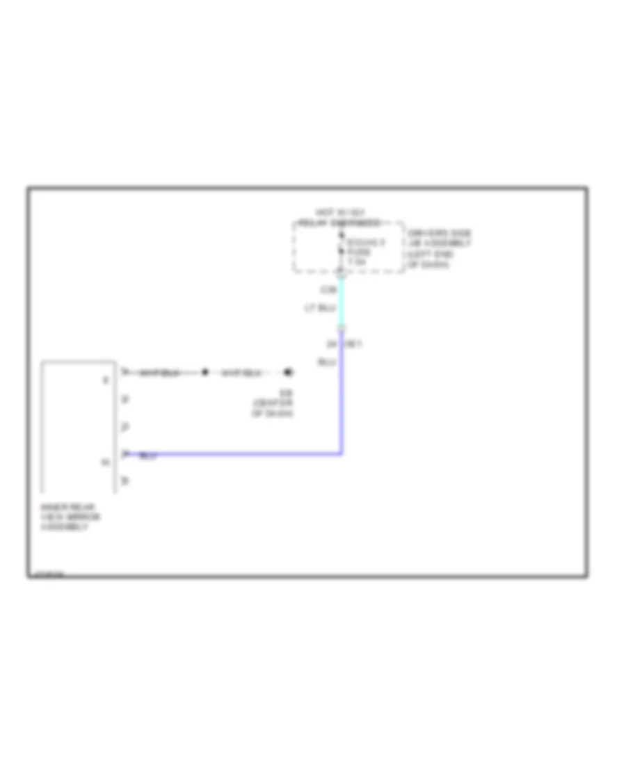
DEFOGGERS
Defoggers Wiring Diagram for Toyota Corolla L 2014
List of elements for Defoggers Wiring Diagram for Toyota Corolla L 2014:
- A/c amplifier assembly (automatic a/c) (center of dash)
- A/c control assembly (automatic a/c)
- A43
- A46
- Ab (behind left headlight)
- Ae6
- Al2
- Automatic a/c
- D35
- D36
- D42
- D45
- Def fuse 50a
- Def relay
- Driver's side j/b assembly (left end of dash)
- E37
- Ea (left kick panel)
- Eb (center of dash)
- Ec (right kick panel)
- Ed (right side of dash)
- Engine room r/b (left side of engine compt)
- Ge1
- Gnd
- He1
- Heater control sub-assembly 2 (manual a/c) (center of dash)
- Hot at all times
- Hot w/ ig1 1 relay energized
- Htr-ig fuse 10a
- Ig+
- L27
- Left outer rear view mirror assembly
- Lin1
- Manual a/c
- Mir htr fuse 10a
- Mirror heater
- Noise filter (radio setting condenser) (left "d" pillar)
- Qa (right "c" pillar)
- Rdef
- Rdfg
- Rear window defogger (back window glass)
- Rear window defogger switch
- Right outer rear view mirror assembly
- Timer circuit
- W/ mirror heater
ELECTRONIC POWER STEERING
Electronic Power Steering Wiring Diagram for Toyota Corolla L 2014
List of elements for Electronic Power Steering Wiring Diagram for Toyota Corolla L 2014:
- (left end of dash) ae
- 5v +b
- 5v ic
- A25
- A44
- Bat
- C18
- C55
- Can i/f
- Canh
- Canl
- Combination meter assembly
- Computer data lines system
- Cpu
- D22
- D30
- D40
- Driver's side junction block assembly (left end of dash)
- E40
- E43
- Ecu-b 2 fuse 7.5a
- Ecu-ig 3 fuse 7.5a
- Ecu-ig 4 fuse 5a
- Ed (right side of dash)
- Engine room relay block (left side of engine compt)
- Eps fuse 80a
- Ess
- Hot at all times
- Hot w/ ig1 relay energized
- Hot w/ ig2 relay energized
- Led driver
- Meter fuse 5a
- Pgnd
- Pig
- Pnk
- Power steering ecu (behind instrument cluster)
- Power steering ind
- Power steering motor
- Power steering motor assembly (left end of dash)
- Power steering torque sensor
- Power steering torque sensor (steering column assembly)
- Red
- Steering sensor (steering column assembly)
- Trq1
- Trq2
- Trqg
- Trqv
ENGINE PERFORMANCE
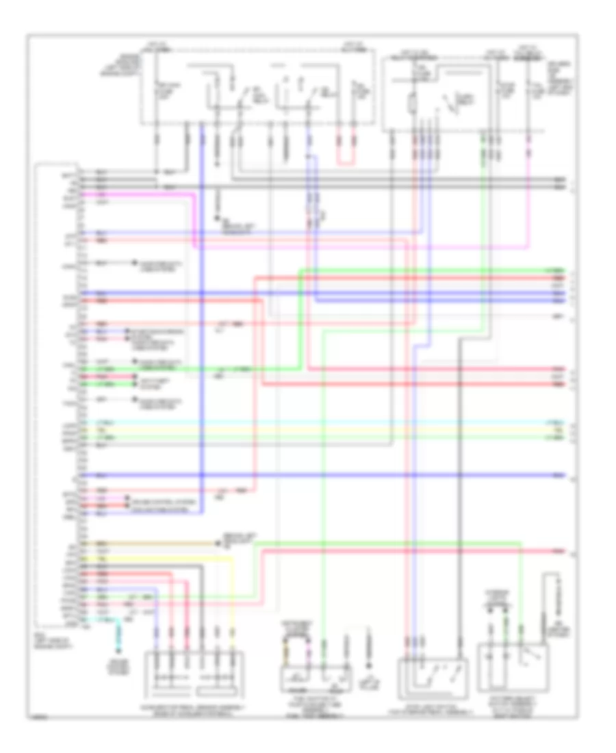
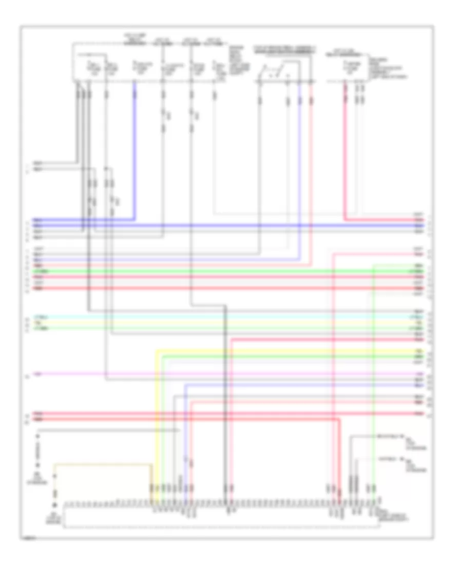
1.8L
1.8L, Engine Performance Wiring Diagram, with Dual VVT-I (1 of 7) for Toyota Corolla L 2014
List of elements for 1.8L, Engine Performance Wiring Diagram, with Dual VVT-I (1 of 7) for Toyota Corolla L 2014:
- (behind left headlight) ab
- +b2
- A14
- A19
- A35
- A36
- A37
- A40
- Ab (behind left headlight)
- Accelerator pedal sensor assembly (base of accelerator pedal)
- Ae2
- Ae3
- Al1
- Anti-theft system
- Ba2
- Batt
- C/opn relay
- Canh
- Canl
- Ccs
- Computer data lines system
- Cooling fans system
- Cruise control system
- Driver's side j/b assembly (left end of dash)
- E36
- Eb (center of dash)
- Ecm (left side of engine compt)
- Efi main fuse 20a
- Efi main relay
- Els1
- Els2
- Engine room r/b (left side of engine compt)
- Epa
- Epa2
- Eppm
- Fuel suction w/ pump & gauge tube assembly (fuel tank assembly)
- Gauge
- Hot at all times
- Hot w/ ig2 relay energized
- Hot w/ tail relay energized
- Ig2 fuse 15a
- Ig2 relay
- Ign fuse 7.5a
- Igsw
- Imi
- Imo
- Instrument cluster system
- Interior lights system
- La (left ''b'' pillar)
- Mpmp
- Mrel
- Pattern select switch assembly (cvt w/ paddle shift switch)
- Pnk
- Ppmp
- Pump
- Pwms
- Red
- Rfc
- Sdsw
- Sftd
- Sftu
- Spd
- St1-
- Sta
- Starting/charging system computer data lines system
- Stop fuse 10a
- Stop light switch (top of brake pedal assembly)
- Stp
- Tach
- Tail fuse 10a
- Vcp2
- Vcpa
- Vcpp
- Vpa
- Vpa2
- Vpmp
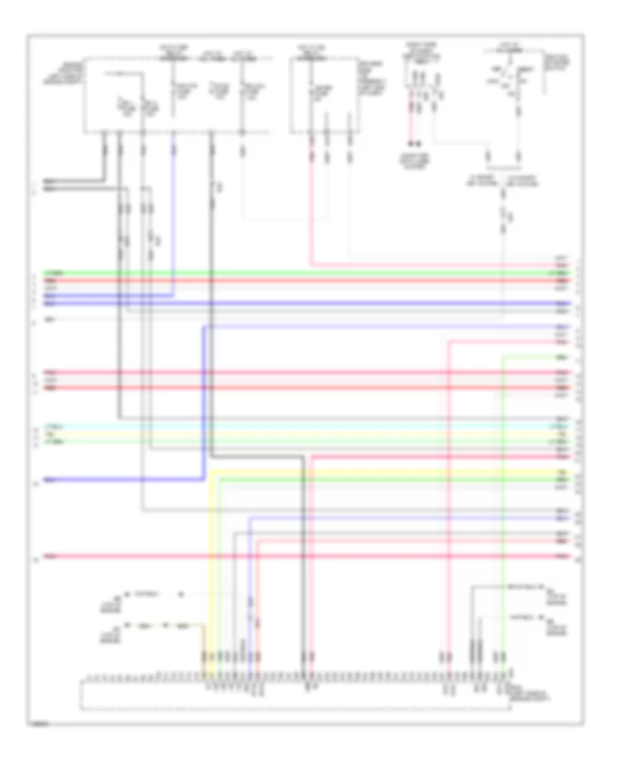
1.8L, Engine Performance Wiring Diagram, with Dual VVT-I (2 of 7) for Toyota Corolla L 2014
List of elements for 1.8L, Engine Performance Wiring Diagram, with Dual VVT-I (2 of 7) for Toyota Corolla L 2014:
- (right side of dash) certification ecu
- +10
- +20
- +30
- +40
- +bm
- A44
- Acc
- Ae3
- B33
- Ba (top of engine)
- Ba1
- Ba2
- Bb (top of engine)
- C55
- Canh
- Canl
- Computer data lines system
- D40
- Driver's side j/b assembly (left end of dash)
- E01
- E02
- E04
- E57
- E59
- Ecm (left side of engine compt)
- Ecu b 2 fuse 7.5a
- Efi 1 fuse 10a
- Efi 2 fuse 10a
- Engine room r/b (left side of engine compt)
- Etcs fuse 10a
- Ha1a
- Hot at all times
- Hot w/ def relay energized
- Hot w/ ig2 relay energized
- Ht1b
- Ig2
- Ig2d
- Ignition/ starter switch
- Igt3
- Igt4
- Lock off
- Meter fuse 5a
- Mir htr fuse 10a
- Pnk
- Red
- Slu+
- Slu-
- Start
- W/ smart key system
- W/o smart key system
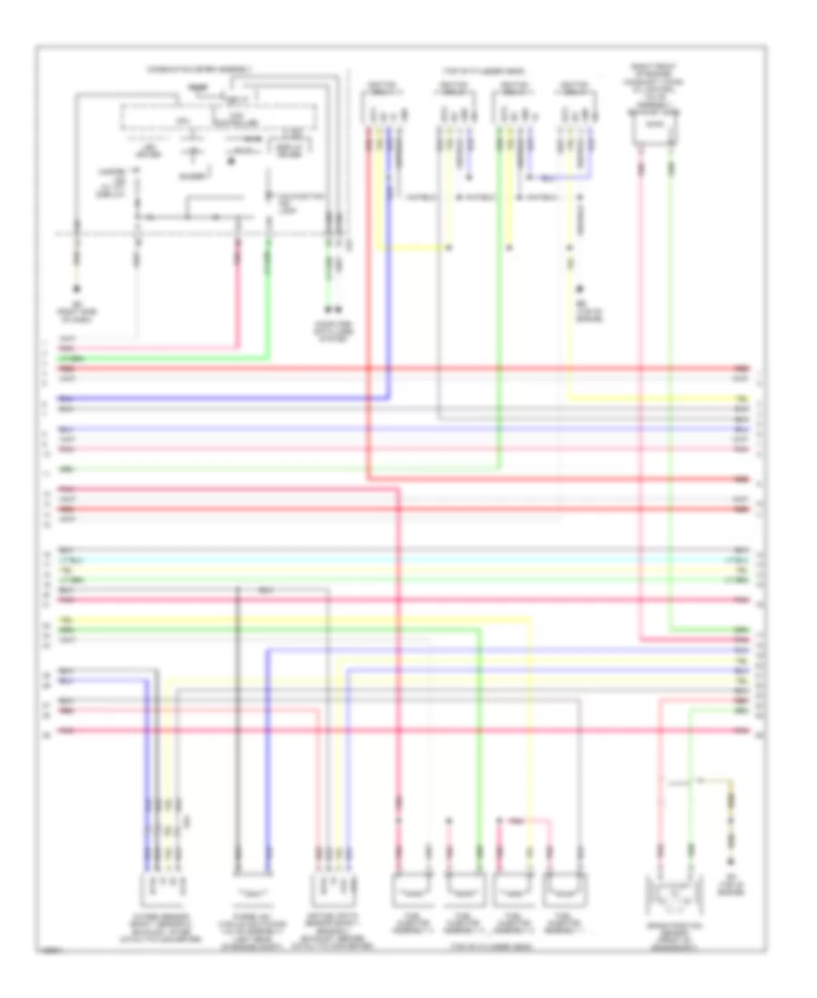
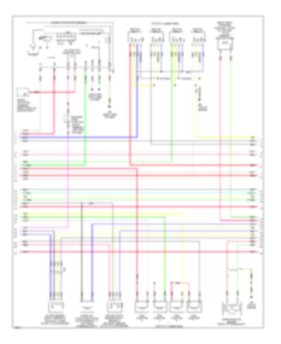
1.8L, Engine Performance Wiring Diagram, with Dual VVT-I (3 of 7) for Toyota Corolla L 2014
List of elements for 1.8L, Engine Performance Wiring Diagram, with Dual VVT-I (3 of 7) for Toyota Corolla L 2014:
- (right front of engine) camshaft timing oil control valve assembly (exhaust side)
- (top of cylinder head)
- 5v ic
- 5v+b
- A1a+
- A1a-
- Ae4
- Air fuel ratio sensor (bank 1 sensor 1) (exhaust, before catalytic converter)
- Ba (top of engine)
- Bb (top of engine)
- Buzzer
- Can controller
- Can i/f
- Canh
- Canl
- Chk
- Combination meter assembly
- Computer data lines system
- Cpu
- Crank position sensor (front of crankshaft)
- Display driver
- E43
- Ed (right side of dash)
- Fuel injector assembly 1
- Fuel injector assembly 2
- Fuel injector assembly 3
- Fuel injector assembly 4
- Gnd
- Ha1a
- Ht1b
- I/f
- Ig+
- Igf
- Ignition coil 1
- Ignition coil 2
- Ignition coil 3
- Ignition coil 4
- Igt1
- Igt2
- Igt3
- Igt4
- Led driver
- Malfunction ind lamp
- Master ind (w/ tft display)
- Ox1b
- Oxygen sensor (bank 1 sensor 2) (exhaust, after catalytic converter)
- Pnk
- Purge vsv (vacuum switching valve assembly) (left rear of engine compt)
- Red
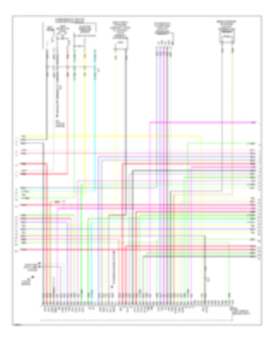
1.8L, Engine Performance Wiring Diagram, with Dual VVT-I (4 of 7) for Toyota Corolla L 2014
List of elements for 1.8L, Engine Performance Wiring Diagram, with Dual VVT-I (4 of 7) for Toyota Corolla L 2014:
- (intake duct) intake mass air flow meter sub-assembly
- (rear of engine) e.f.i engine coolant temperature sensor
- (right front of engine) camshaft timing oil control valve assembly (intake side)
- (top of clutch pedal assembly) (m/t) clutch start switch
- (under rear of vehicle) canister pump module
- A/t
- A/t & cvt
- Al1
- Alt
- B33
- Ba (top of engine)
- Ba1
- Ba2
- Canister pressure sensor
- Cvt
- Cvt w/o paddle
- E2g
- Ecm (left side of engine compt)
- Etho
- Ethw
- Ev1+
- Ge01
- Igf1
- Igt1
- Igt2
- Leak detection pump
- M/t
- Me01
- Ne+
- Ne-
- Nsw
- Oc1+
- Oc1-
- Oe1+
- Oe1-
- Ox1b
- Pnk
- Prg
- Pto
- Red
- Shift switch
- Slp+
- Slp-
- Sls+
- Sls-
- Slt+
- Slt-
- System starting/charging
- Tha
- Tho1
- Thw
- Vent valve
- Vta1
- Vta2
- Vv1+
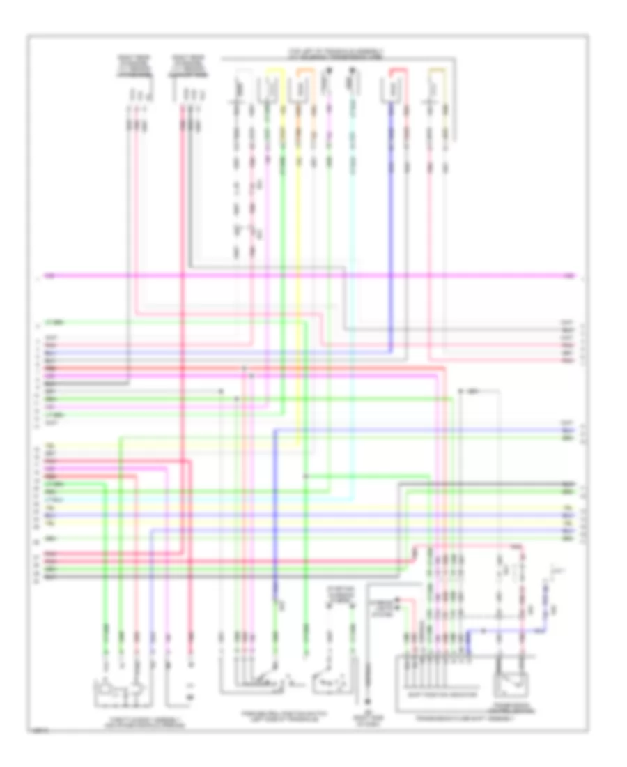
1.8L, Engine Performance Wiring Diagram, with Dual VVT-I (5 of 7) for Toyota Corolla L 2014
List of elements for 1.8L, Engine Performance Wiring Diagram, with Dual VVT-I (5 of 7) for Toyota Corolla L 2014:
- (left side of transaxle) (a/t) electronically controlled transmission solenoid (transmission wire)
- (top left of transaxle assembly) (cvt) cvt solenoid (transmission wire)
- A/t
- Ae4
- At3
- Ba1
- Ba2
- Cvt
- Cvt w/o paddle shift switch
- Ed (right side of dash)
- Ill+
- Ill-
- Interior lights system
- J/c a38
- Nssd
- Ntb
- Nto
- Park/neutral position switch (left side of transaxle)
- Pnk
- Red
- Shift position indicator
- Slp+
- Slp-
- Sls+
- Sls-
- Slt+
- Slt-
- Slu+
- Slu-
- Starting/ charging system
- Tho
- Throttle body assembly (air intake manifold opening)
- Transmission control switch (w/o paddle shift switch)
- Transmission floor shift assembly
- Vta
- Vta2
1.8L, Engine Performance Wiring Diagram, with Dual VVT-I (6 of 7) for Toyota Corolla L 2014
List of elements for 1.8L, Engine Performance Wiring Diagram, with Dual VVT-I (6 of 7) for Toyota Corolla L 2014:
- (center console) (cvt & a/t) diode (backup light)
- (left side of engine block) knock control sensor (bank 1)
- (on transmission case) (cvt) oil pressure sensor
- (right rear of engine) vvt sensor (intake side)
- A/t
- A45
- A56
- Acc fuse 7.5a
- Ae2
- Ba (top of engine)
- Bd1
- Cvt
- Driver's side j/b assembly (left end of dash)
- Ecu-ig 2 fuse 10a
- Hot w/ acc relay energized
- Hot w/ ig1 1 relay energized
- J/c a38
- Nca
- Pnk
- Pto
- Red
- Transmission revolution sensor (primary) (left side of transaxle case)
- Transmission revolution sensor (secondary) (cvt) (right side of transmission case)
- Transmission revolution sensor (turbine)
- Vc2
- Vve+
- Vve-
- Vvi+
- Vvi-
- Vvt sensor (exhaust side) (right rear of engine)
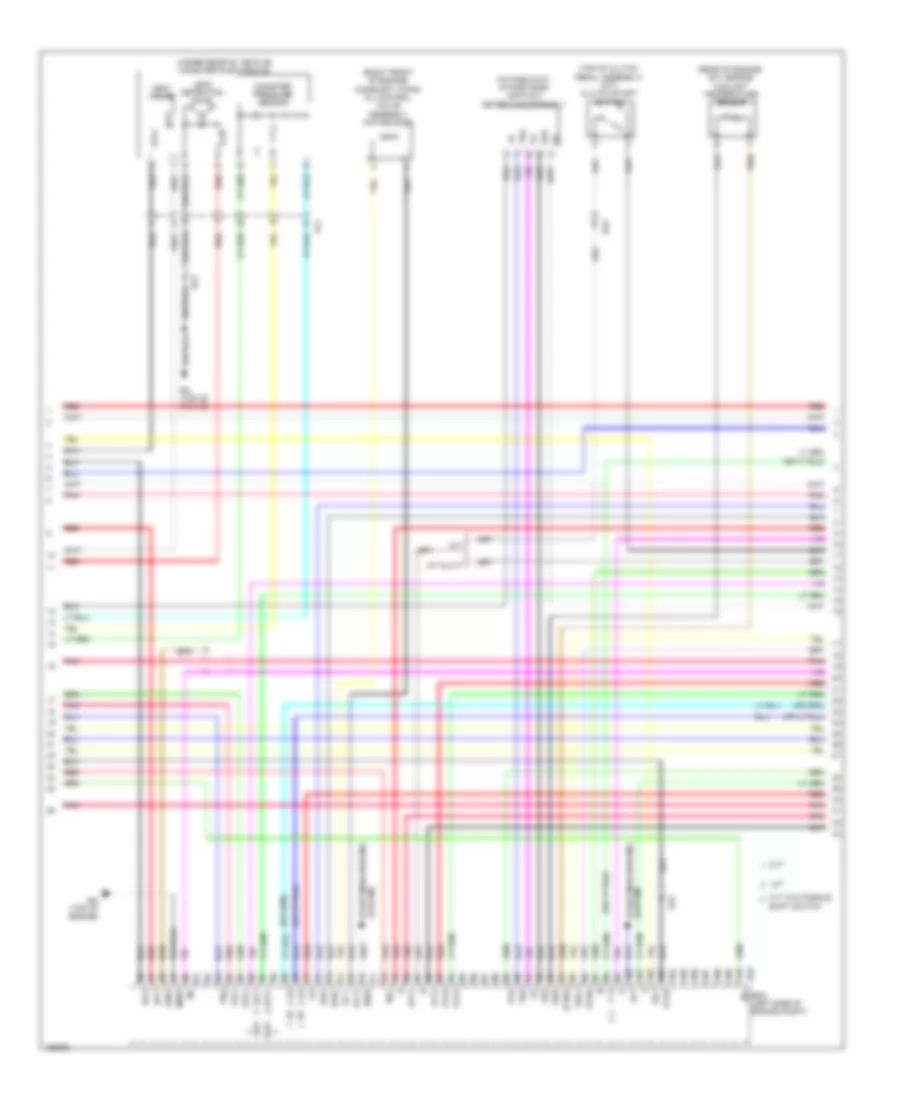
1.8L, Engine Performance Wiring Diagram, with Dual VVT-I (7 of 7) for Toyota Corolla L 2014
List of elements for 1.8L, Engine Performance Wiring Diagram, with Dual VVT-I (7 of 7) for Toyota Corolla L 2014:
- (left side of engine compt) ecm
- A/t
- A1a+
- A1a-
- A20
- Ae2
- Ae3
- B33
- Ba (top of engine)
- Ba1
- C39
- Cvt
- Down
- Driver's side j/b assembly (left end of dash)
- Eb (center of dash)
- Ecta
- Ecu-ig 3 fuse 7.5a
- Eknk
- Epto
- Eta
- Etha
- Ev1-
- Ex1b
- Hot w/ ig1 1 relay energized
- J/c a38
- Knk1
- Left steering pad switch assembly
- Nin+
- Nin-
- Notb
- Noto
- Nt+
- Nt-
- Ntb
- Nto
- Pnk
- Red
- Right steering pad switch assembly
- Sftd
- Sftu
- Spiral cable sub-assembly (steering column)
- Steering pad switch assembly
- Transmission control switch (transmission floor shift assembly) (cvt w/ paddle shift switch) (under center console)
- Transmission shift switch assembly
- Vce1
- Vcpt
- Vcv1
- Vv1-
- W/ cruise control
- Z10
1.8L, Engine Performance Wiring Diagram, with Valvematic (1 of 6) for Toyota Corolla L 2014
List of elements for 1.8L, Engine Performance Wiring Diagram, with Valvematic (1 of 6) for Toyota Corolla L 2014:
- (behind left headlight) ab
- +b2
- A19
- A35
- A36
- A37
- A40
- Ab (behind left headlight)
- Accelerator pedal sensor assembly (base of accelerator pedal)
- Ae3
- Al1
- Al2
- Anti-theft system
- Ba2
- Batt
- Can+
- Can-
- Canh
- Canl
- Ccs
- Computer data lines system
- Continuously variable valve lift controller assembly (rear of engine compt)
- Cooling fans system
- Cruise control system
- Door locks system
- Driver's side junction block assembly (left end of dash)
- Ecm (left side of engine compt)
- Efi- main relay
- Efi-main fuse 20a
- Els1
- Els2
- Engine room relay block (left side of engine compt)
- Epa
- Epa2
- Eppm
- Fp-
- Fpc
- Fuel pump control ecu assembly (left rear luggage compt)
- Fuel suction w/ pump & gauge tube assembly (fuel tank assembly)
- Gauge
- Hall ic
- Hot at all times
- Hot w/ ig2 relay energized
- Hot w/ tail relay energized
- Ign fuse 7.5a
- Igsw
- Igt/ inj relay
- Imi
- Imo
- Inj fuse 15a
- Instrument cluster system
- Mpmp
- Mrel
- Neo
- Pnk
- Ppmp
- Pump
- Red
- Rfc
- Sdsw
- Sdwn
- Spd
- St1-
- Sta
- Starting/charging system computer data lines system
- Stop fuse 10a
- Stp
- Tach
- Tail fuse 10a
- Vcp2
- Vcpa
- Vcpp
- Vpa
- Vpa2
- Vpmp
1.8L, Engine Performance Wiring Diagram, with Valvematic (2 of 6) for Toyota Corolla L 2014
List of elements for 1.8L, Engine Performance Wiring Diagram, with Valvematic (2 of 6) for Toyota Corolla L 2014:
- (top of brake pedal assembly) stop light switch assembly
- +bm
- A44
- B33
- Ba (top of engine)
- Ba1
- Ba2
- Ba3
- Bb (top of engine)
- C55
- D40
- Driver's side junction block assembly (left end of dash)
- E01
- E02
- E04
- Ecm (left side of engine compt)
- Ecu- b 2 fuse 7.5a
- Efi 1 fuse 10a
- Efi 2 fuse 10a
- Engine room relay block (left side of engine compt)
- Etcs fuse 10a
- Ha1a
- Hot at all times
- Hot w/ def relay energized
- Hot w/ ig2 relay energized
- Ht1b
- Igt3
- Igt4
- Meter fuse 5a
- Mir htr fuse 10a
- Pnk
- Red
- Sdwn
- Slu+
- Slu-
- Vlvmatic fuse 30a
1.8L, Engine Performance Wiring Diagram, with Valvematic (3 of 6) for Toyota Corolla L 2014
List of elements for 1.8L, Engine Performance Wiring Diagram, with Valvematic (3 of 6) for Toyota Corolla L 2014:
- (right front of engine) camshaft timing oil control valve assembly (exhaust side)
- (top of cylinder head)
- 5v ic
- 5v+b
- A1a+
- A1a-
- A48
- Ae4
- Air fuel ratio sensor (bank 1 sensor 1) (exhaust, before catalytic converter)
- Ba (top of engine)
- Bb (top of engine)
- Brake actuator assembly (right front of engine compt)
- Buzzer
- Can controller
- Can i/f
- Canh
- Canl
- Chk
- Combination meter assembly
- Computer data lines system
- Cpu
- Crank position sensor (front of crankshaft)
- D28
- Display driver
- Driver's side junction block assembly (left end of dash)
- E43
- Ed (right side of dash)
- Fuel injector
- Gnd
- Ha1a
- Ht1b
- I/f
- Ig+
- Igf
- Ignition coil 1
- Ignition coil 2
- Ignition coil 3
- Ignition coil 4
- Igt1
- Igt2
- Igt3
- Igt4
- Malfunction indicator lamp
- Ox1b
- Oxygen sensor (bank 1 sensor 2) (exhaust, after catalytic converter)
- Pnk
- Purge vsv (vacuum switching valve assembly 1) (left rear of engine compt)
- Red
- Sp1
1.8L, Engine Performance Wiring Diagram, with Valvematic (4 of 6) for Toyota Corolla L 2014
List of elements for 1.8L, Engine Performance Wiring Diagram, with Valvematic (4 of 6) for Toyota Corolla L 2014:
- (intake duct) intake mass air flow meter sub- assembly
- (rear of engine) efi engine coolant temperature sensor
- (right front of engine) camshaft timing oil control valve assembly (intake side)
- (under rear of vehicle) canister pump module
- Al1
- B33
- Ba (top of engine)
- Ba1
- Can+
- Can-
- Canister pressure sensor
- Computer data lines system
- E2g
- Ecm (left side of engine compt)
- Etho
- Ethw
- Ev1+
- Ge01
- Igf1
- Igt1
- Igt2
- Leak detection pump
- Me01
- Ne+
- Ne-
- Nsw
- Oc1+
- Oc1-
- Oe1+
- Oe1-
- Ox1b
- Pim
- Pnk
- Prg
- Pto
- Red
- Slp+
- Slp-
- Sls+
- Sls-
- Starting/charging system
- Tha
- Tho1
- Thw
- Vcvs
- Vent valve
- Vsm
- Vta1
- Vta2
- Vv1+
1.8L, Engine Performance Wiring Diagram, with Valvematic (5 of 6) for Toyota Corolla L 2014
List of elements for 1.8L, Engine Performance Wiring Diagram, with Valvematic (5 of 6) for Toyota Corolla L 2014:
- (right rear of engine) vvt sensor (exhaust side)
- (right rear of engine) vvt sensor (intake side)
- (top left of transaxle assembly) cvt solenoid (transmission wire)
- Ae2
- Ae4
- At3
- Ba1
- Ba2
- D n
- Ed (right side of dash)
- Ill+
- Ill-
- Interior lights system
- J/c 1
- Nssd
- Ntb
- Nto
- Park/neutral position switch (left side of transaxle)
- Pnk
- R n
- Red
- Shift position indicator
- Slp+
- Slp-
- Sls+
- Sls-
- Slu+
- Slu-
- Starting/ charging system
- Tho
- Throttle body assembly (air intake manifold opening)
- Transmission control switch
- Transmission floor shift assembly
- Vc2
- Vta
- Vta2
- Vv1+
- Vve+
- Vve-
- Vvi-
1.8L, Engine Performance Wiring Diagram, with Valvematic (6 of 6) for Toyota Corolla L 2014
List of elements for 1.8L, Engine Performance Wiring Diagram, with Valvematic (6 of 6) for Toyota Corolla L 2014:
- (left rear of engine) e.f.i vacuum sensor assembly
- (left side of engine block) knock control sensor (bank 1)
- (on transmission case) oil pressure sensor
- A1a+
- A1a-
- A45
- A56
- Acc fuse 7.5a
- Ae2
- B33
- Ba (top of engine)
- Ba1
- Bd1
- Diode (backup light) (center console)
- Driver's side junction block assembly (left end of dash)
- E2vs
- Ecm (left side of engine compt)
- Ecu- ig 2 fuse 10a
- Eknk
- Epim
- Epto
- Eta
- Etha
- Ethe
- Ev1-
- Ex1b
- Gnd
- Hot w/ acc relay energized
- Hot w/ ig1 1 relay energized
- J/c a38
- Knk1
- Nca
- Nin+
- Nin-
- Notb
- Noto
- Ntb
- Nto
- Oil temperature sensor (front of engine)
- Pim
- Pnk
- Pto
- Red
- Theo
- Transmission revolution sensor (primary) (left side of transaxle case)
- Transmission revolution sensor (secondary) (right side of transmission case)
- Valve event angle control shaft monitor sensor (crank position sensor 1) (rear of engine)
- Vcc
- Vce1
- Vcpm
- Vcpt
- Vcta
- Vcv1
- Vout
- Vv1-
EXTERIOR LIGHTS
Backup Lamps Wiring Diagram for Toyota Corolla L 2014
List of elements for Backup Lamps Wiring Diagram for Toyota Corolla L 2014:
- A/t
- A/t & cvt
- A40
- A42
- A45
- A56
- Ab (behind left headlight)
- Acc
- Acc fuse 7.5a
- Ae2
- Ae4
- B33
- Ba1
- Ba2
- Backup
- Backup light switch assembly (transaxle assembly)
- Bkup lp relay (a/t & cvt)
- Canh
- Canl
- Computer data lines system
- Cvt
- Diode (backup light) (a/t & cvt) (center console)
- Driver side junction block assembly (left end of dash)
- Ecm (left side of engine compt)
- Ecu-ig 2 fuse
- Engine room relay block (left side of engine compt)
- Hot in on or acc
- Hot in on or start
- Ig/acc
- Ig1
- J/c 1
- Lb (left "c" pillar)
- Left rear light assembly
- M/t
- Park/neutral position switch (left side of transaxle)
- Red
- Right rear light assembly
- Shift position indicator
- Transmission floor shift assembly (cvt)
- W/ dual vvt-i
- W/ valvematic
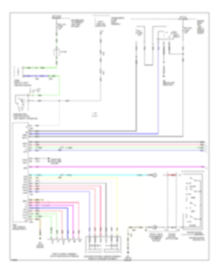
Exterior Lamps Wiring Diagram (1 of 2) for Toyota Corolla L 2014
List of elements for Exterior Lamps Wiring Diagram (1 of 2) for Toyota Corolla L 2014:
- (canada w/ tft display) tail ind
- (top of brake pedal assembly) stop light switch
- 5v ic
- 5v+b
- A18
- A19
- A35
- A40
- A44
- Ae3
- Brake actuator assembly (right front of engine compt)
- Buzzer
- C55
- Can controller
- Can h
- Can i/f
- Can l
- Center stop light assembly
- Combination meter assembly
- Computer data lines system
- Cpu
- Cruise control system
- D13
- D31
- D33
- D34
- D39
- D40
- Driver's side junction block assembly (left end of dash)
- E11
- E26
- E27
- E43
- E47
- Ea (left kick panel)
- Ecm (left side of engine compt)
- Ecu-b 2 fuse 7.5a
- Ecu-b fuse 10a
- Ed (right side of dash)
- Engine room relay block (left side of engine compt)
- Ge1
- Haz
- He1
- Hot at all times
- Hot w/ ig2 relay energized
- I/f
- Ig+
- L21
- L22
- Lb (left "c" pillar)
- Led driver
- Left license plate light assembly
- Left outer rear view mirror assembly (w/ outer rear view mirror side turn signal light)
- Left rear combination light assembly
- Left turn ind
- Meter fuse 5a
- Noise filter (radio setting condenser) (left "d" pillar)
- Pnk
- Red
- Right license plate light assembly
- Right outer rear view mirror assembly (w/ outer rear view mirror side turn signal light)
- Right rear combination turn light assembly
- Right turn ind
- Stop
- Stop fuse 10a
- Stp
- Tail/side marker
- Turn
- Turn & haz fuse 10a
- Gl1
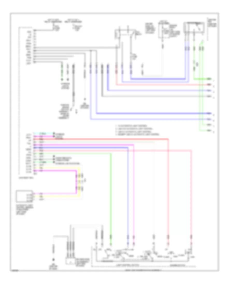
Exterior Lamps Wiring Diagram (2 of 2) for Toyota Corolla L 2014
List of elements for Exterior Lamps Wiring Diagram (2 of 2) for Toyota Corolla L 2014:
- (left end of dash) driver's side junction block assembly
- A14
- A20
- A21
- A24
- Aa (behind left headlight)
- Ac (behind right headlight)
- Acc
- Acc fuse 7.5a
- Alt fuse 120a
- Auto drl
- Becu
- C15
- C36
- Canh
- Canl
- Certification ecu (w/ smart key system) (right side of dash)
- Computer data lines system
- D12
- D16
- D17
- Driver's side junction block assembly (left end of dash)
- Drl off off
- E29
- E31
- E34
- E57
- Ea (left kick panel)
- Eb (center of dash)
- Ecu ig 1 fuse 7.5a
- Ed (right side of dash)
- Engine room junction block (left side of engine compt)
- Except usa w/ automatic light control
- Flcy
- Frcy
- Gnd1
- Hazard warning signal
- Head
- Headlight dimmer switch assembly
- Hot at all times
- Hot w/ acc relay energized
- Hot w/ ig1 1 relay energized
- Interior lights system
- Lcty
- Left
- Left headlight assembly
- Light control switch
- Main body ecu
- Panel fuse 5a
- Parking
- Pnk
- Rcty
- Red
- Right
- Right headlight assembly
- Shift lock control ecu (transmission floor shift assembly) (under center console)
- Side marker
- Stp
- Stp1
- Switch assembly
- Tail
- Tail fuse 10a
- Tail relay
- Trly
- Turn
- Turn switch
- Usa w/ automatic light control
- Usa w/o automatic light control
- W/ automatic light control
- W/ smart key system
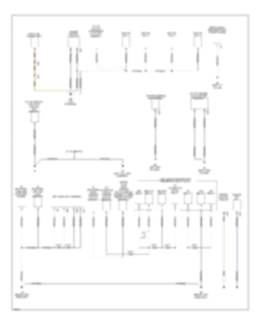
GROUND DISTRIBUTION
Ground Distribution Wiring Diagram (1 of 5) for Toyota Corolla L 2014
List of elements for Ground Distribution Wiring Diagram (1 of 5) for Toyota Corolla L 2014:
- (if equipped) left fog light assembly
- (if equipped) level warning switch assembly
- (if equipped) wireless door lock buzzer
- (left side of engine compt) engine room relay block
- (w/ a/c switch) compressor w/ pulley assembly
- (w/ ptc heater) quick heater assembly
- (w/ valvematic) fuel pump control ecu assembly
- (w/ valvematic) igt/inj relay
- (w/ valvematic) vacuum warning switch assembly
- A/t & cvt
- A10
- A21
- A25
- A28
- A30
- A31
- A40
- Aa (behind left headlight)
- Ab (behind left headlight)
- Ae (left end of dash)
- Ae4
- Af (right end of dash)
- B33
- Ba1
- Bb (top of engine)
- Bkup lp relay
- Brake fluid level warning switch (brake master cylinder reservoir sub- assembly)
- Cooling fan
- Data link connector 3
- Def relay
- Ecu
- Efi-main relay
- Engine control module
- Fan relay 1
- Ig2 relay
- Ignition coil 1
- Ignition coil 2
- Ignition coil 3
- Ignition coil 4
- Le (left tail light assembly)
- Left headlight assembly
- Power steering ecu assembly
- Qa (right "c" pillar)
- Rear window defogger (back window glass)
- St relay 1
- W/ valvematic
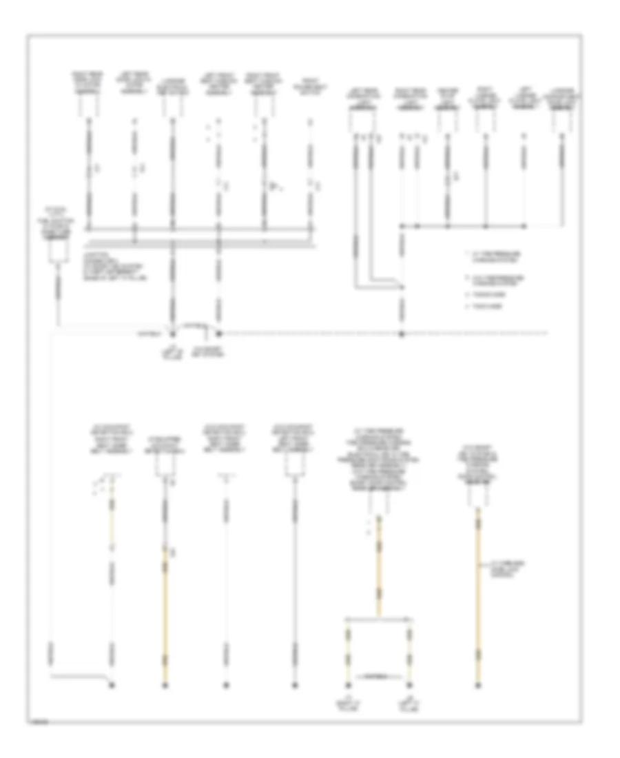
Ground Distribution Wiring Diagram (2 of 5) for Toyota Corolla L 2014
List of elements for Ground Distribution Wiring Diagram (2 of 5) for Toyota Corolla L 2014:
- (if equipped) occupant detection ecu
- (w/ dual vvt-i) fuel suction w/ pump & gage tube assembly
- (w/ occupant detection ecu)
- (w/ tire pressure warning system) tire pressure warning ecu & receiver (electrical key & tire pressure monitoring system receiver assembly) (w/o tire pressure warning system) smart door control receiver assembly
- (w/o occupant detection ecu) left front seat inner belt assembly
- (w/o occupant detection ecu) right front seat inner belt assembly
- (w/o smart key system & tire pressure warning system) door control receiver
- Center stop light assembly
- Front power seat switch
- Jl1
- Junction connector 4 (w/ smart key system & theft deterrent) (base of left "c" pillar)
- Kl1
- L21
- L22
- La (left "b" pillar)
- Lb (left "c" pillar)
- Lc (right "c" pillar)
- Left front seat cushion heater assembly
- Left license plate light assembly
- Left rear combination light assembly
- Left rear door lock w/ motor assembly
- Ls1
- Ls2
- Lt1
- Luggage compartment door lock assembly
- Luggage electrical key switch
- Right front seat cushion heater assembly
- Right front seat inner belt assembly
- Right license plate light assembly
- Right rear combination light assembly
- Right rear door lock w/ motor assembly
- Tmmc made
- Tmmms made
- W/ tire pressure warning system
- W/ wireless door lock control
- W/o smart key system
- W/o tire pressure warning system
- Gl1
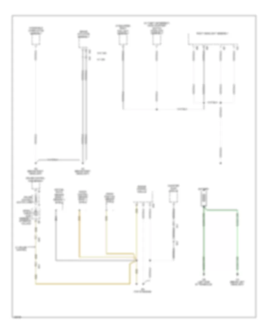
Ground Distribution Wiring Diagram (3 of 5) for Toyota Corolla L 2014
List of elements for Ground Distribution Wiring Diagram (3 of 5) for Toyota Corolla L 2014:
- (if equipped) right fog light assembly
- (w/ theft deterrent) hood courtesy switch (hood lock assembly)
- A14
- A20
- A27
- A29
- A41
- A42
- Ac (behind right headlight)
- Ad (behind right headlight)
- Ae3
- Air fuel ratio sensor (bank 1 sensor 1) shield
- Al1
- B33
- Ba (top of engine)
- Ba1
- Battery
- Brake actuator assembly
- Ca (behind left headlight)
- Canister pump module
- Cb (left side of transaxle)
- Crank position sensor shield
- Cruise control main switch
- Cruise control switch wire
- Engine control module
- Knock control sensor (bank 1) shield
- Nca
- Right headlight assembly
- Spiral cable sub- assembly (steering column)
- W/ cruise control
- W/ vsc
- W/o vsc
- Windshield
- Wiper motor assembly
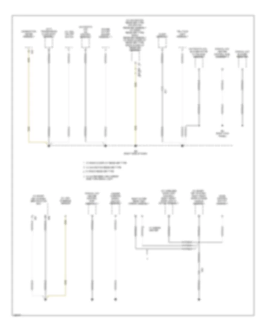
Ground Distribution Wiring Diagram (4 of 5) for Toyota Corolla L 2014
List of elements for Ground Distribution Wiring Diagram (4 of 5) for Toyota Corolla L 2014:
- (automatic a/c)
- (automatic a/c) a/c control assembly
- (cvt) transmission floor shift assembly
- (manual a/c)
- (manual a/c) blower resistor
- (w/ navigation receiver type) navigation receiver assembly (w/ radio receiver type) radio receiver assembly (w/ radio & display receiver type) radio & display receiver assembly
- (w/ smart key system)
- (w/ smart key system) certification ecu
- (w/ vsc)
- (w/ vsc) vsc off switch
- (w/ wireless door lock control) right front door lock w/ motor assembly
- Blower motor w/ fan sub- assembly
- Clock assembly
- Combination meter assembly
- Door control switch assembly
- E43
- E57
- E58
- E62
- E65
- Ec (right kick panel)
- Ed (right side of dash)
- Ef1
- Ge1
- Hazard warning signal switch assembly
- Heater control sub- assembly 1
- Heater control sub- assembly 2
- Power outlet socket assembly 1
- Right front door outside handle assembly
- Right outer rear view mirror assembly
- Steering sensor
- Telltale light assembly
- W/ mirror heater
- W/ navigation receiver type
- W/ outer rear view mirror side turn signal light
- W/ radio & display receiver type
- W/ radio receiver type
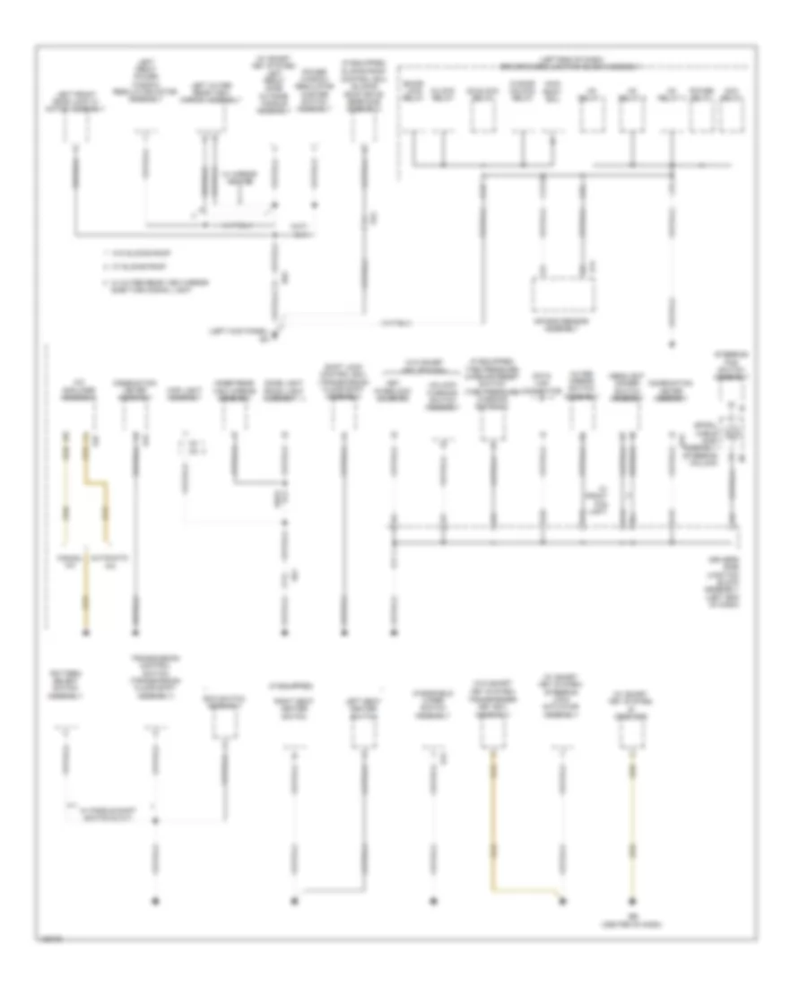
Ground Distribution Wiring Diagram (5 of 5) for Toyota Corolla L 2014
List of elements for Ground Distribution Wiring Diagram (5 of 5) for Toyota Corolla L 2014:
- (if equipped)
- (if equipped) tire pressure warning reset switch (tire pressure warning switch 1)
- (left end of dash) driver's side junction block assembly
- (left kick panel) ea
- (transmission floor shift assembly)
- (w/ smart key system) id code box
- (w/ smart key system) left front door outside handle assembly
- (w/ smart key system) steering lock actuator assembly
- (w/o smart key system)
- A/c amplifier assembly
- Acc relay
- Air bag sensor assembly
- Automatic a/c
- Bk/dr lock relay
- C26
- C47
- Combination meter assembly
- D door unlock relay
- D/lock relay
- D/unlock relay
- D12
- D16
- D17
- D18
- D19
- D20
- Data link connector
- Dome light (room light assembly 1)
- Driver's side junction block assembly (left end of dash)
- E12
- E14
- E37
- E43
- Eb (center of dash)
- Eco switch assembly
- He2
- Headlight dimmer switch assembly
- Ig1 relay 1
- Ig1 relay 2
- Ig1 relay 3
- Inner rear view mirror assembly
- Key interlock solenoid
- Left front door lock w/ motor assembly
- Left front power window regulator motor assembly
- Left outer rear view mirror assembly
- Left seat heater switch
- Main body ecu
- Manual a/c
- Map light assembly
- O3 o5
- Oe1
- Outer mirror switch assembly
- Pattern select switch assembly
- Power relay
- Power window regulator master switch assembly
- Right seat heater switch
- Shift lock control ecu
- Side turn signal light
- Sliding roof control ecu (sliding roof drive gear sub- assembly)
- Spiral cable sub- assembly (steering column)
- Steering pad switch assembly
- Transmission control switch (transmission floor shift assembly)
- Transponder key ecu assembly
- Un-lock warning switch assembly
- W/ front fog light
- W/ mirror heater
- W/ outer rear view mirror
- W/ paddle shift switch & cvt
- W/ sliding roof
- W/o sliding roof
- Windshield wiper switch assembly
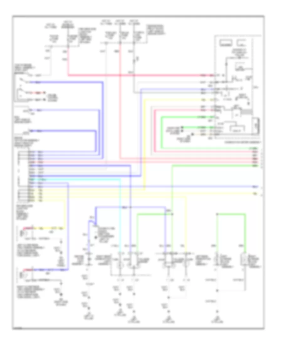
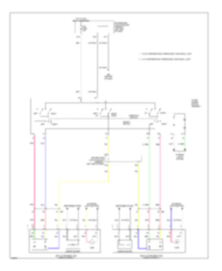
HEADLIGHTS
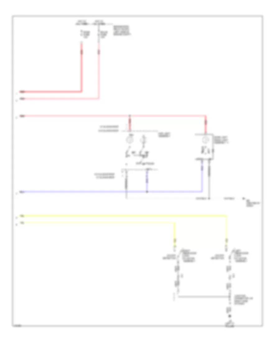
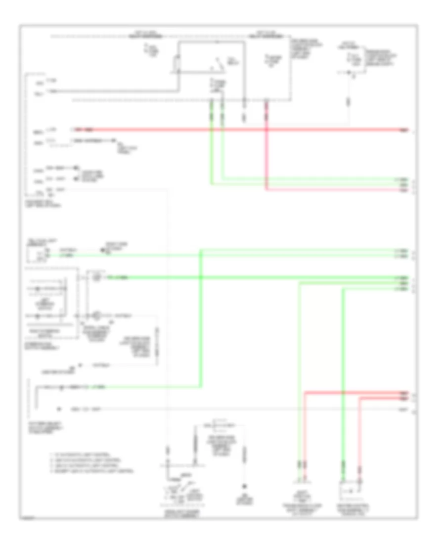
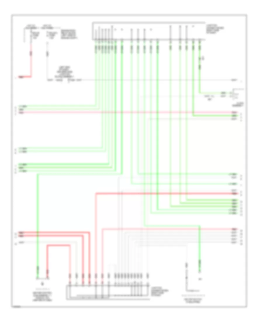
Headlights Wiring Diagram (1 of 2) for Toyota Corolla L 2014
List of elements for Headlights Wiring Diagram (1 of 2) for Toyota Corolla L 2014:
- A24
- A28
- A34
- A49
- A50
- Acc
- Acc fuse 7.5a
- Ae6
- Alt fuse 120a
- Auto drl
- Automatic light control sensor (if equipped) (left side of dash)
- Becu
- Bfg
- C43
- Canh
- Canl
- Center r/b (center of dash)
- Cltb
- Clte
- Clts
- Computer data lines system
- D16
- D17
- D37
- Dim
- Dimmer switch
- Driver side j/b assembly (left end of dash)
- Driver's side j/b assembly (left end of dash)
- Drl
- Drl off off
- E30
- E31
- E34
- E38
- Eb (center of dash)
- Ecu-ig 1 fuse 7.5a
- Ef1
- Engine room j/b (left side of engine compt)
- Except usa w/ automatic light control
- Ffgo
- Ffog
- Flash
- Flcy
- Fog switch
- Fr fog relay
- Frcy
- Gnd1
- Head
- Headlight dimmer switch assembly
- High
- Hot at all times
- Hot w/ acc relay energized
- Hot w/ ig1 1 relay energized
- Hrly
- Interior lights system
- Lcty
- Lfg
- Lgcy
- Light control switch
- Low
- Main body ecu
- Parking brake switch assembly (base of lever assembly)
- Pkb
- Pnk
- Rcty
- Red
- Tail
- Tail fuse 10a
- Tail relay
- Trly
- Usa w/ automatic light control
- Usa w/o automatic light control
- W/ automatic light control
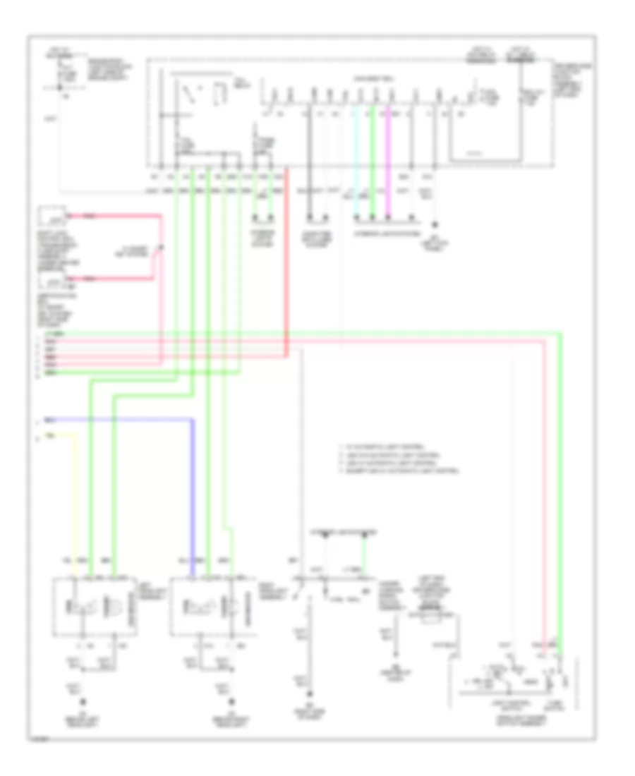
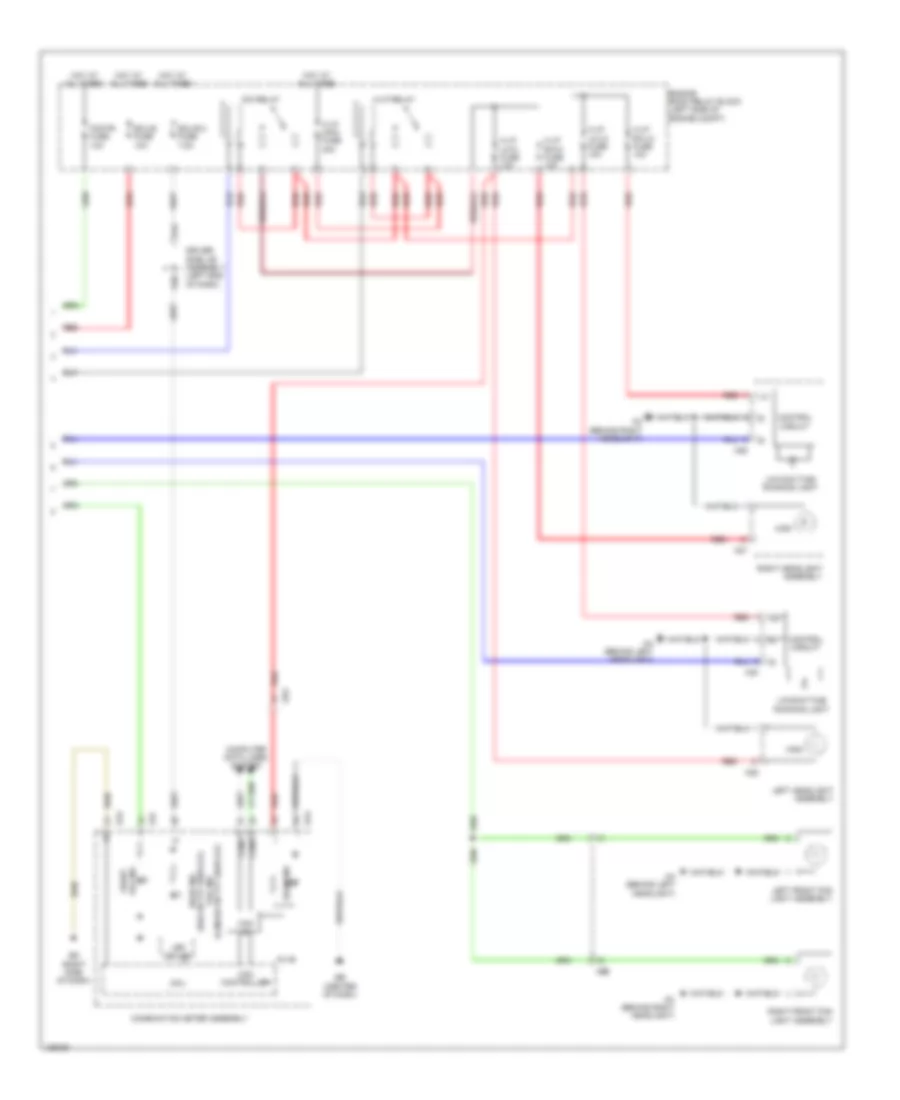
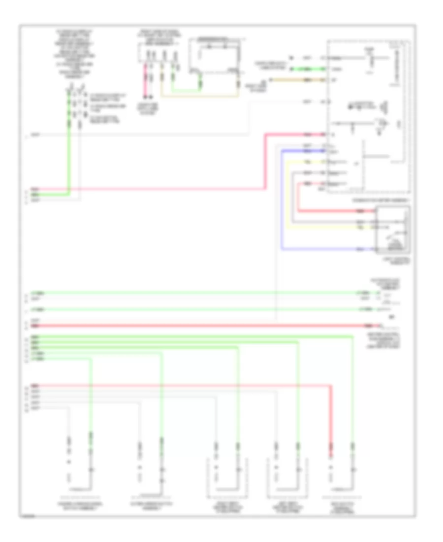
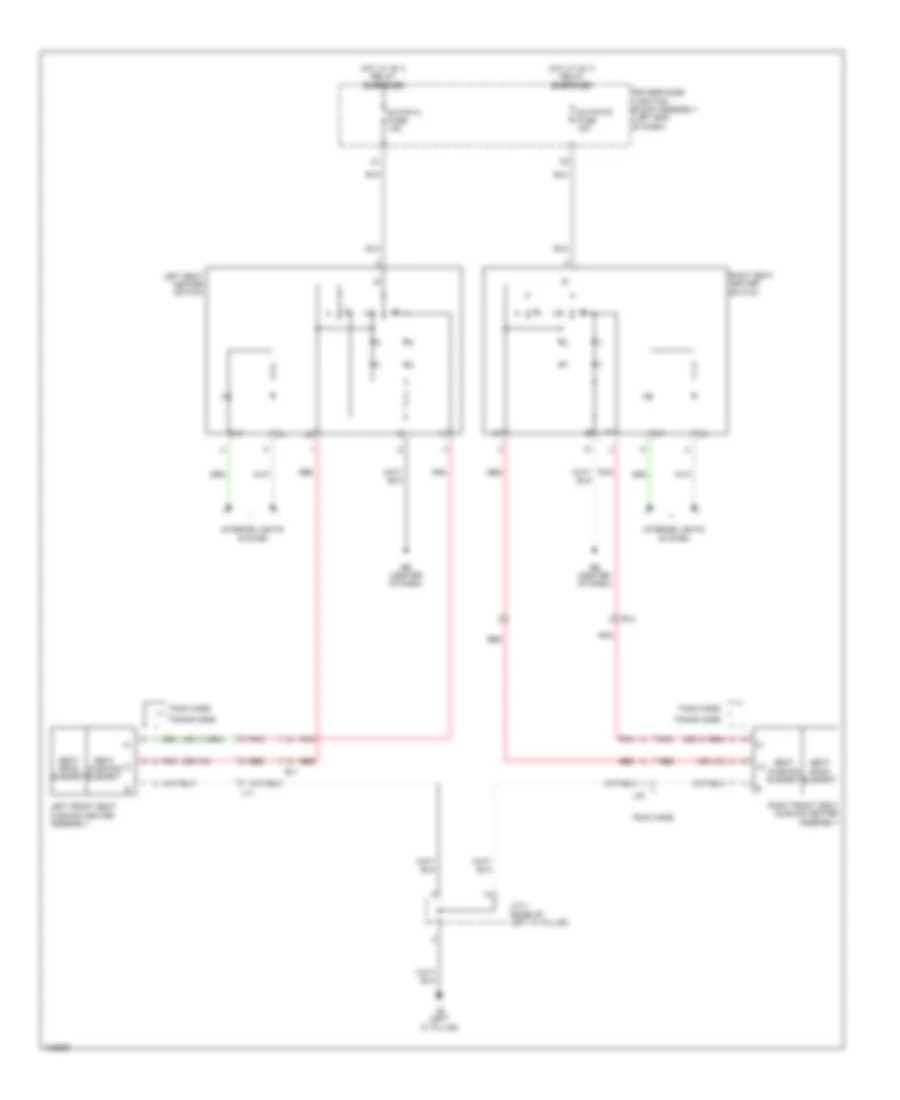
Headlights Wiring Diagram (2 of 2) for Toyota Corolla L 2014
List of elements for Headlights Wiring Diagram (2 of 2) for Toyota Corolla L 2014:
- (canada w/ tft display) tail ind
- (usa w/ tft display) head ind
- 5v+b
- A27
- A28
- A29
- A30
- A44
- Aa (behind left headlight)
- Ac (behind right headlight)
- Ae3
- Ae6
- Beam ind
- Can controller
- Can i/f
- Canh
- Canl
- Combination meter assembly
- Computer data lines system
- Control circuit
- Cpu
- D40
- Dim relay
- Driver side j/b assembly (left end of dash)
- E43
- E47
- Eb (center of dash)
- Ecu-b 2 fuse 7.5a
- Ecu-b fuse 10a
- Ed (right side of dash)
- Engine room relay block (left side of engine compt)
- Fog fr fuse 10a
- Fog ind front
- H-lp lh-hi fuse 10a
- H-lp lh-lo fuse 10a
- H-lp main fuse 40a
- H-lp relay
- H-lp rh-hi fuse 10a
- H-lp rh-lo fuse 10a
- High
- Hot at all times
- Led driver
- Left front fog light assembly
- Left headlight assembly
- Low/daytime running light
- Red
- Right front fog light assembly
- Right headlight assembly
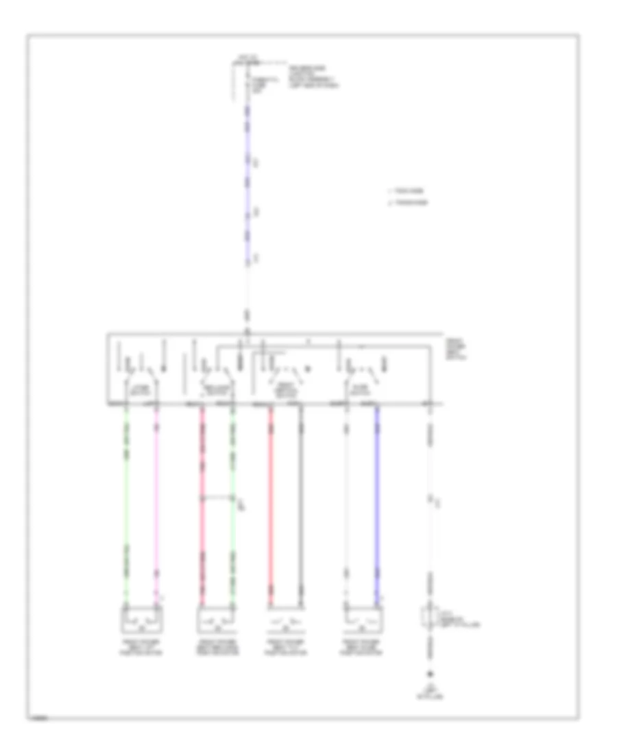
HORN
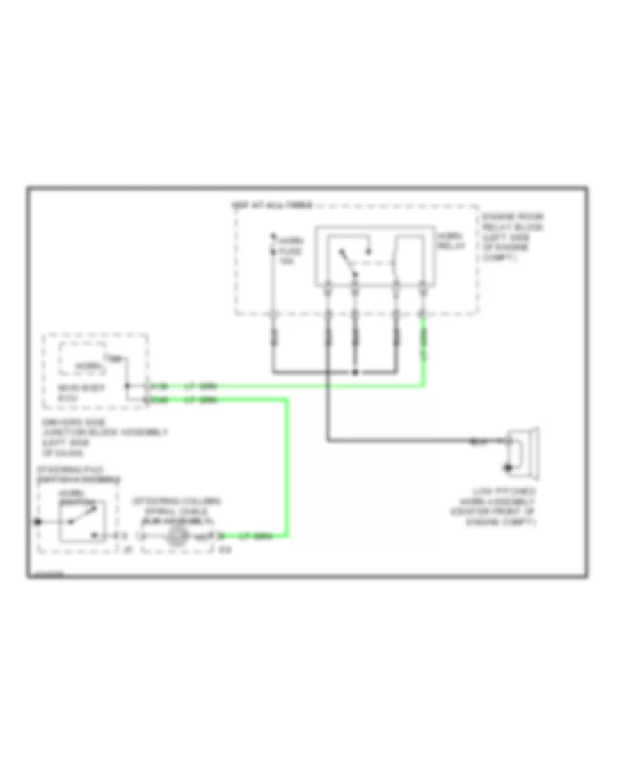
Horn Wiring Diagram for Toyota Corolla L 2014
List of elements for Horn Wiring Diagram for Toyota Corolla L 2014:
- (steering column) spiral cable sub-assembly
- A38
- C49
- Driver's side junction block assembly (left side of dash)
- Engine room relay block (left side of engine compt)
- Horn
- Horn fuse 10a
- Horn relay
- Horn switch
- Hot at all times
- Low pitched horn assembly (center front of engine compt)
- Main body ecu
- Steering pad switch assembly
INSTRUMENT CLUSTER
Instrument Cluster Wiring Diagram (1 of 3) for Toyota Corolla L 2014
List of elements for Instrument Cluster Wiring Diagram (1 of 3) for Toyota Corolla L 2014:
- (front of engine) engine oil pressure switch assembly
- (if equipped) cruise ind
- (if equipped) tire pressure ind
- (if equipped) vsc off ind
- (if equipped) washer ind
- (usa) trac off ind (canada) trc off ind
- (w/ vsc) slip ind
- (w/o tft display)
- (w/o tft display) charge ind
- (w/o tft display) eco ind
- (w/o tft display) fuel ind
- 5v ic
- 5v+b
- A10
- A11
- A12
- A13
- A14
- A15
- A16
- A17
- A19
- A21
- A28
- A29
- A31
- A32
- A33
- A34
- A35
- A36
- A37
- A39
- A40
- Abs ind
- Ae3
- Anti-lock brakes system
- B10
- B12
- B13
- Ba1
- Beam ind
- Brake ind
- Buzzer
- Can controller
- Can i/f
- Canh
- Canl
- Chg-
- Chk
- Combination meter assembly
- Computer data lines system
- Cpu
- D17
- D18
- Display driver
- Display) switch & tft (w/ paddle shift sport ind
- Door ind (w/o tft display)
- Driver's side junction block assembly (left end of dash)
- E43
- Eb (center of dash)
- Eco ind (w/ tft display)
- Eco mode ind (w/o tft display w/ eco switch)
- Ed (right side of dash)
- Electrical key ind (w/ smart key system w/o tft display)
- Engine controls system
- Front fog ind
- Fuel ind (w/ tft display)
- Head ind (usa w/ tft display) tail ind (canada w/ tft display)
- Headlight dimmer switch assembly
- Headlights system
- Hi water temperature ind
- I/f
- Ig+
- Ill-
- Illumination ind
- Ind lamp malfunction
- Indicator)
- Interior lights system
- Led driver
- Left turn ind
- Master ind (w/ tft display)
- Oil pressure ind (w/o tft display)
- P/sb
- Pnk
- Power steering ind
- Red
- Right turn ind
- Seat belt ind
- Set ind (w/ cruise control)
- Srs ind
- Starting/charging system
- Sw1
- Sw2
- Sw3
- Tx1+
- Tx1-
- W/ oil maintenance (w/o tft display & maint reqd ind
- W/ tft display
- W/ tft display & level warning switch
- W/o tft display
- Warning systems
- Wiper/washer system
- Wlvl
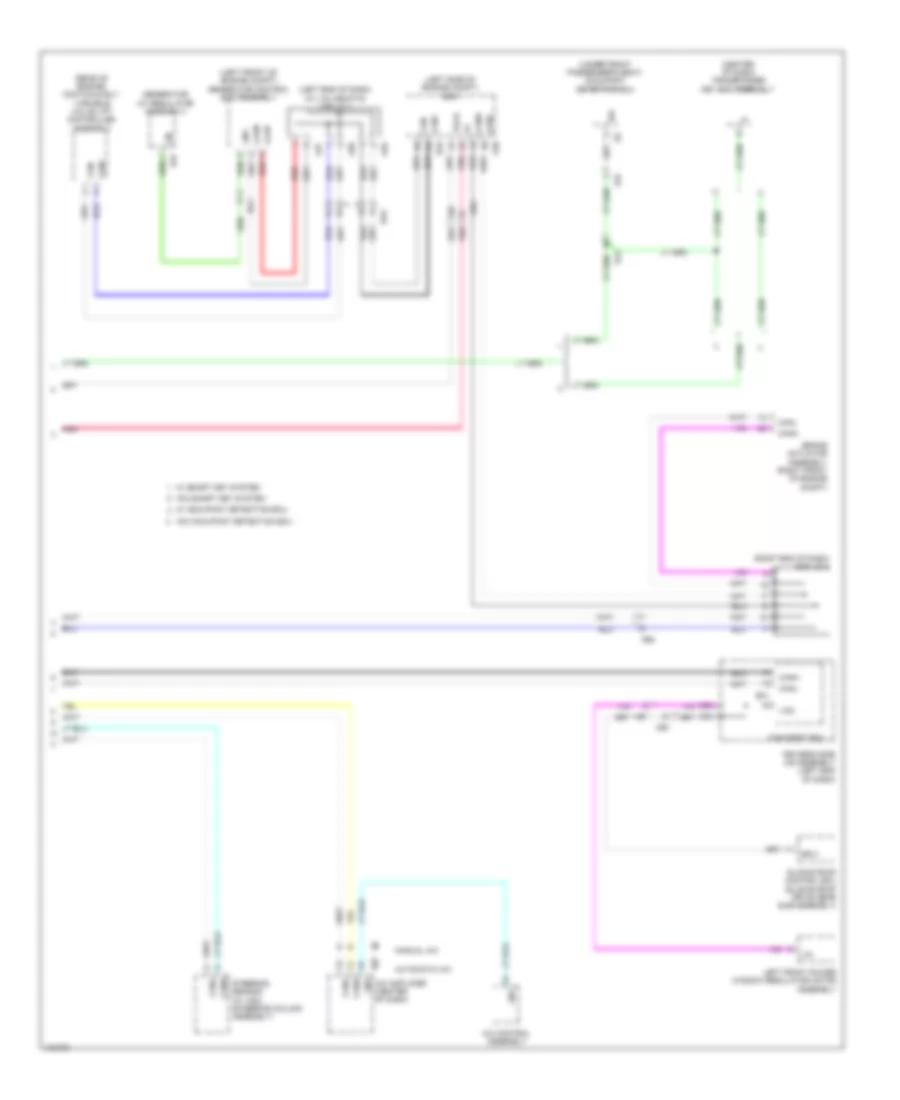
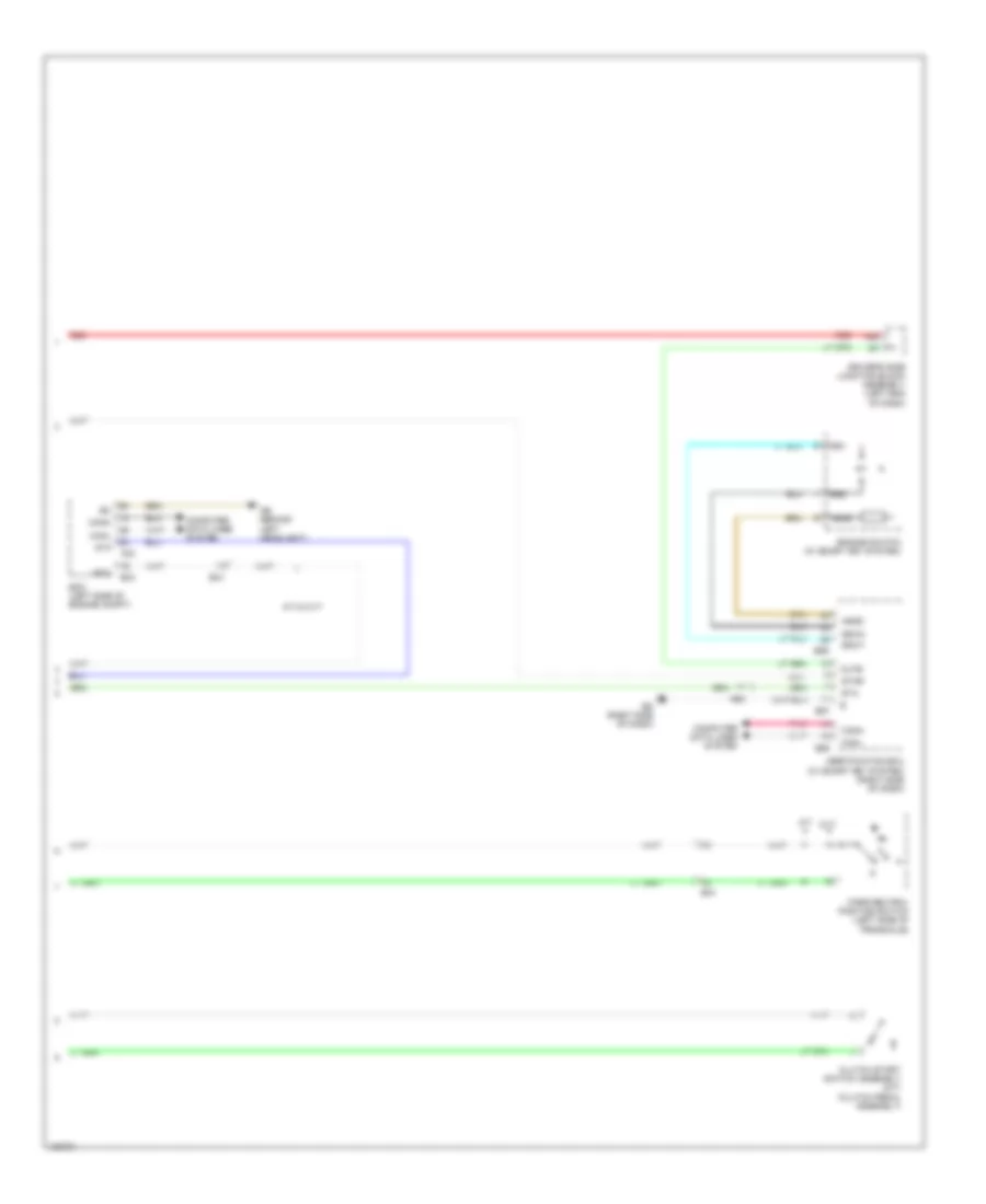
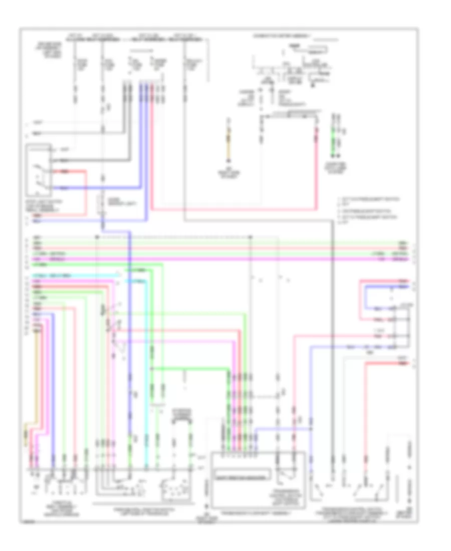
Instrument Cluster Wiring Diagram (2 of 3) for Toyota Corolla L 2014
List of elements for Instrument Cluster Wiring Diagram (2 of 3) for Toyota Corolla L 2014:
- (fuel tank assembly) fuel suction w/ pump & gauge tube assembly
- A44
- Ab (behind left headlight)
- Ae3
- Ambient temperature sensor (thermistor assembly) (front of engine compt)
- Brake fluid level warning switch (brake master cylinder reservoir sub assembly) (brake fluid reservoir)
- C55
- Combination meter assembly
- D17
- D40
- Disp
- Driver's side junction block assembly (left end of dash)
- E47
- Eb (center of dash)
- Ecu-b 2 fuse 7.5a
- Ecu-b fuse 10a
- El1
- Engine room relay block (left side of engine compt)
- Exterior lights system
- Fog
- Gauge
- Haz
- Headlights system
- Hot at all times
- Hot w/ ig2 relay energized
- J/c 1
- Left steering switch
- Meter fuse 5a
- Pnk
- Red
- Right steering switch
- Spiral cable sub assembly (steering column)
- Steering pad switch assembly
- Turn & haz fuse 10a
- Vacuum warning switch assembly (w/ valvematic) (left rear of engine compt)
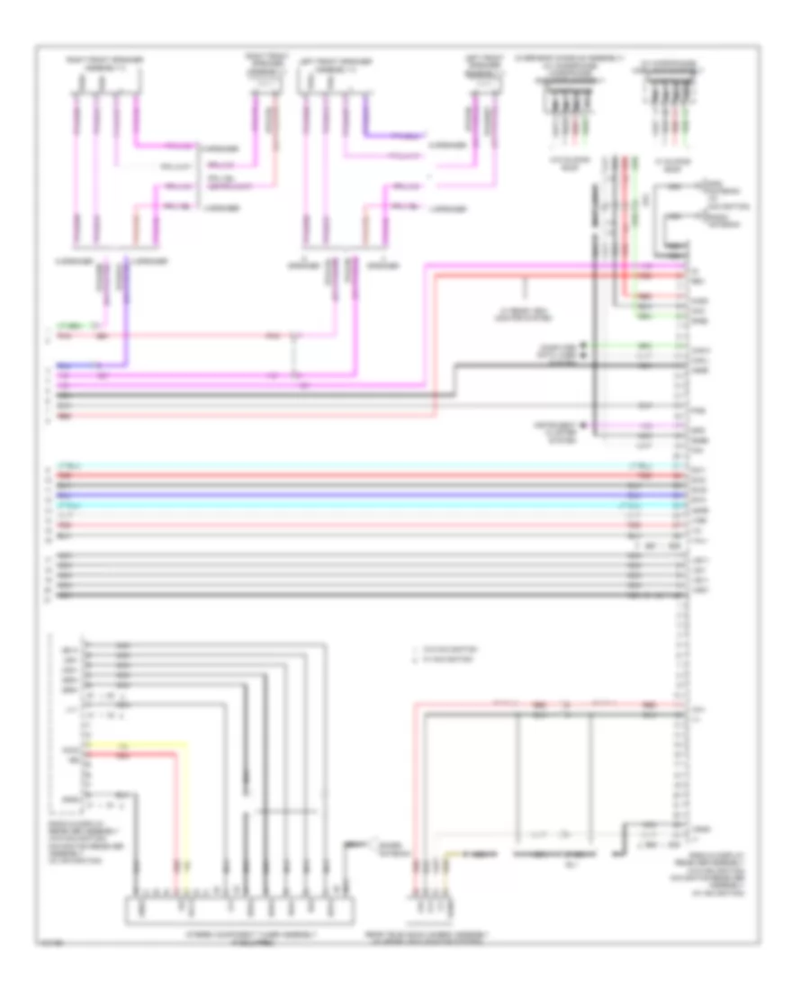
- W/ dual vvt-i
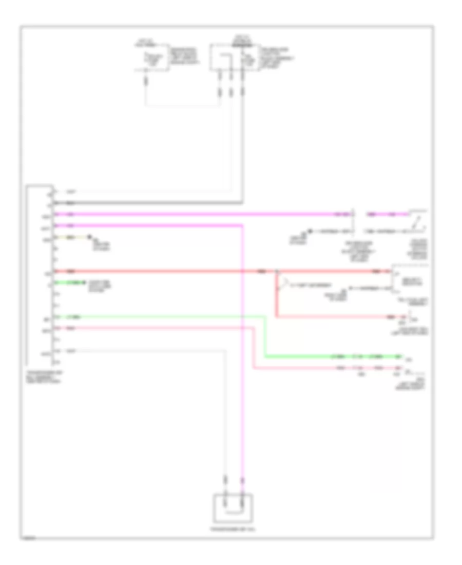
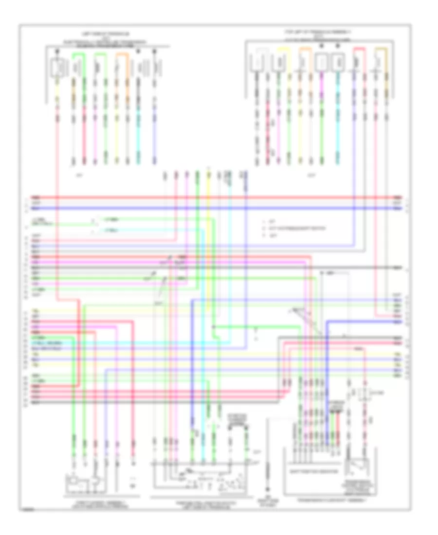
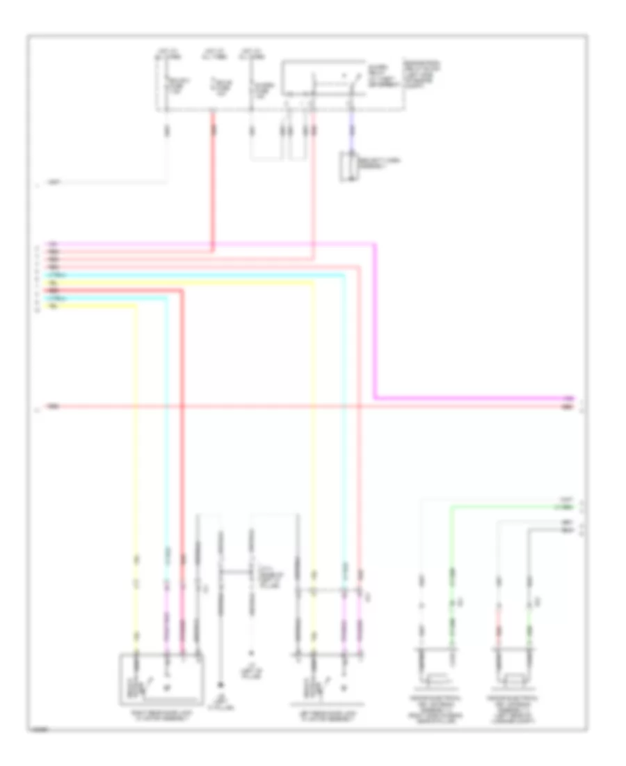
- W/ valvematic
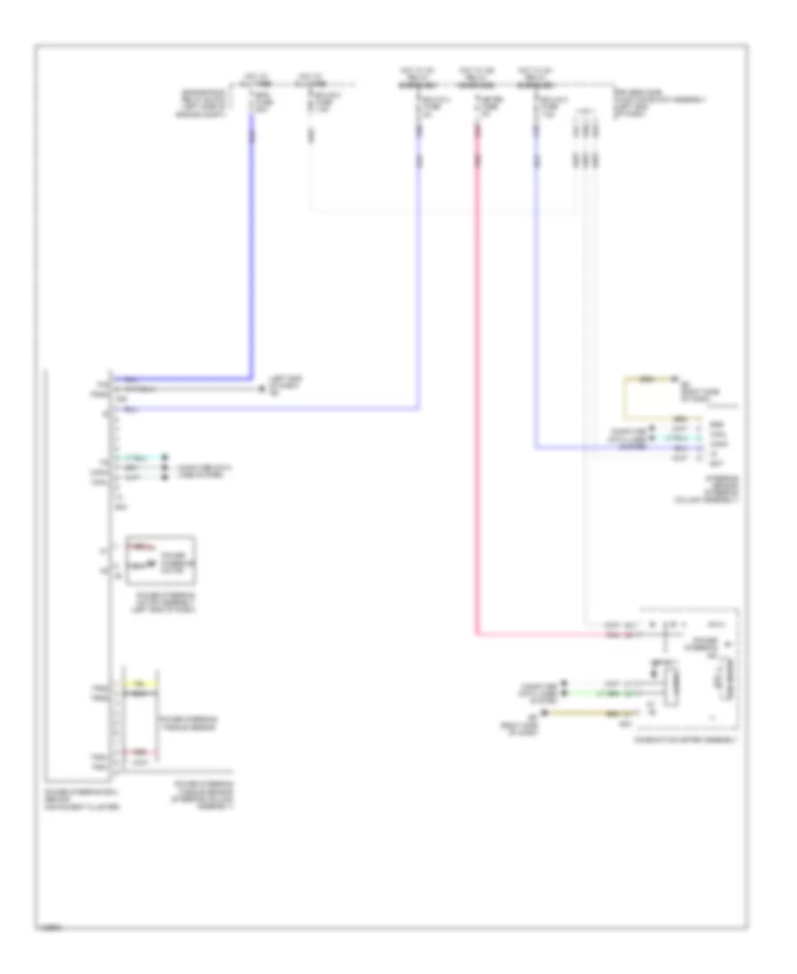
Instrument Cluster Wiring Diagram (3 of 3) for Toyota Corolla L 2014
List of elements for Instrument Cluster Wiring Diagram (3 of 3) for Toyota Corolla L 2014:
- A24
- A40
- A48
- Acc
- Acc fuse 7.5a
- Becu
- C23
- C41
- Canh
- Canl
- Certification ecu (w/ smart key system) (right side of dash)
- Clock assembly
- Computer data lines system
- D11
- D12
- D28
- D29
- D32
- Driver's side junction block assembly (left end of dash)
- E29
- E30
- E31
- E34
- E59
- E64
- E67
- Ea (left kick panel)
- Ecm (left side of engine compt)
- Ecu-ig 1 fuse 7.5a
- Ed (right side of dash)
- Ef1
- El1
- El2
- Flcy
- Frcy
- Gnd1
- Hot w/ acc relay energized
- Hot w/ ig1 1 relay energized
- Ill+
- Ill-
- Interior lights system
- Lcty
- Left front door courtesy light switch assembly (left "b" pillar)
- Left rear door courtesy light switch assembly (base of left "c" pillar)
- Main body ecu
- Parking brake switch assembly (base of lever assembly)
- Pkb
- Radio receiver assembly (w/ radio receiver type) navigation receiver assembly (w/ navigation receiver type) radio & display receiver assembly (w/ radio & display receiver type)
- Rcty
- Red
- Right front door courtesy light switch assembly (right "b" pillar)
- Right rear door courtesy light switch assembly (base of right "c" pillar)
- Spd
- W/ navigation receiver type
- W/ radio & display receiver type
- W/ radio receiver type
INTERIOR LIGHTS
Courtesy Lamps Wiring Diagram (1 of 2) for Toyota Corolla L 2014
List of elements for Courtesy Lamps Wiring Diagram (1 of 2) for Toyota Corolla L 2014:
- (left kick panel) ea
- (right side of dash) ed
- A24
- A51
- Acc
- Acc fuse 7.5a
- Bctl
- Becu
- C42
- C54
- Canh
- Canl
- Computer data lines system
- D26
- Dome cut relay
- Domr
- Driver's side junction block assembly (left end of dash)
- E24
- E31
- E34
- E38
- E39
- E40
- Eb (center of dash)
- Ecu-ig1 1 fuse 7.5a
- El1
- El2
- Flcy
- Frcy
- Ge1
- Gnd 1
- He2
- Hot w/ acc relay energized
- Hot w/ ig1 1 relay energized
- Ile
- Jl1
- Kl1
- Lb (left "c" pillar)
- Lcty
- Left front door courtesy light switch assembly (left "b" pillar)
- Left front door lock w/ motor assembly
- Left rear door courtesy light switch assembly (base of left "c" pillar)
- Lgcy
- Lgyl bcyl
- Lsfl
- Lsfr
- Lsr
- Luggage compartment courtesy door lock assembly (center of luggage compt)
- Luggage compartment light assembly 1
- Main body ecu
- Oe1
- Pnk
- Rcty
- Red
- Right front door courtesy light switch assembly (right "b" pillar)
- Right front door lock w/ motor assembly
- Right rear door courtesy light switch assembly (base of right "c" pillar)
- Unlock detection
- W/ theft deterrent
- W/o theft deterrent
Courtesy Lamps Wiring Diagram (2 of 2) for Toyota Corolla L 2014
List of elements for Courtesy Lamps Wiring Diagram (2 of 2) for Toyota Corolla L 2014:
- +b1
- Cty
- Dome fuse 10a
- Dome light (room light assembly 1)
- Door
- Eb (center of dash)
- Ecu-b fuse 10a
- Engine room relay block (left side of engine compt)
- Hot at all times
- Jl1
- Junction connector l49 (right side of dash)
- Kl1
- Lb (left 'c" pillar)
- Left rear door lock w/ motor assembly
- Map light assembly
- Off
- Red
- Right rear door lock w/ motor assembly
- Unlock detection
- W/ sliding roof
- W/o sliding roof
Instrument Illumination Wiring Diagram (1 of 3) for Toyota Corolla L 2014
List of elements for Instrument Illumination Wiring Diagram (1 of 3) for Toyota Corolla L 2014:
- (right side of dash) ed
- A24
- Acc
- Acc fuse 7.5a
- Alt fuse 120a
- Auto drl
- Becu
- C15
- C36
- C55
- Canh
- Canl
- Computer data lines system
- D12
- D16
- D17
- Dim
- Driver's side junction block assembly (left end of dash)
- Drl off off
- E31
- Ea (left kick panel)
- Eb (center of dash)
- Engine room junction block (left side of engine compt)
- Except usa w/ automatic light control
- Gnd1
- Head
- Headlight dimmer switch assembly
- Heater control sub-assembly 3 (manual a/c)
- Hot at all times
- Hot w/ acc relay energized
- Hot w/ ig1 relay energized
- Ill-
- Left steering switch
- Light control switch
- Main body ecu (left end of dash)
- Meter fuse 5a
- Msw+
- Msw-
- Panel fuse 5a
- Pattern select switch assembly (if equipped)
- Pnk
- Red
- Right steering switch
- Shift position ind
- Spiral cable sub-assembly (steering column)
- Steering pad
- Switch assembly
- Tail
- Tail relay
- Telltale light assembly
- Transmission floor shift assembly (a/t & cvt)
- Trly
- Usa w/ automatic light control
- Usa w/o automatic light control
- W/ automatic light control
Instrument Illumination Wiring Diagram (2 of 3) for Toyota Corolla L 2014
List of elements for Instrument Illumination Wiring Diagram (2 of 3) for Toyota Corolla L 2014:
- (left end of dash)
- A44
- Clock assembly
- D40
- Driver's side junction block assembly
- Ecu-b 2 fuse 7.5a
- Ecu-b fuse 10a
- Ef1
- Engine room relay block (left side of engine compt)
- Heater control sub-assembly 1 (manual a/c) (center of dash)
- Hot at all times
- Ill+
- Ill-
- Junction connector e53 (right side of dash)
- Junction connector e54 (right side of dash)
- Pnk
- Red
- Vsc off switch (if equipped)
Instrument Illumination Wiring Diagram (3 of 3) for Toyota Corolla L 2014
List of elements for Instrument Illumination Wiring Diagram (3 of 3) for Toyota Corolla L 2014:
- (automatic a/c) a/c control assembly
- (right side of dash) (w/ smart key system) certification ecu assembly
- (w/ radio & display receiver type) radio & display receiver assembly (w/ navigation receiver type) navigation receiver assembly (w/ radio receiver type) radio receiver assembly
- 5v ic
- 5v+b
- Agnd
- Can controller
- Can i/f
- Canh
- Canl
- Combination meter assembly
- Computer data lines system
- Cpu
- E43
- E59
- E62
- E63
- E65
- E66
- Eco switch assembly (if equipped)
- Ed (right side of dash)
- Engine switch
- Hazard warning signal switch assembly
- Heater control sub-assembly 2 (manual a/c) (center of dash)
- I/f
- Ill+
- Ill-
- Illumination
- Led driver
- Left seat heater switch (if equipped)
- Light control rheostat
- Outer mirror switch assembly
- Pnk
- Red
- Right seat heater switch (if equipped)
- Sw1
- Sw2
- Sw3
- Swil
- Tail cancel switch
- W/ navigation receiver type
- W/ radio & display receiver type
- W/ radio receiver type
NAVIGATION
Navigation Wiring Diagram (1 of 3) for Toyota Corolla L 2014
List of elements for Navigation Wiring Diagram (1 of 3) for Toyota Corolla L 2014:
- +b1
- 5v +b
- 5v ic
- 5v+b
- A44
- Acc fuse 7.5a
- Acc1
- Ae3
- Agnd
- Alo
- Aro
- Asgn
- Au1
- Au2
- Auxo
- Back
- C37
- C41
- C55
- Can controller
- Can i/f
- Canh
- Canl
- Combination meter assembly
- Computer data lines system
- Cpu
- D14
- D40
- Down
- Driver's side junction block assembly (left end of dash)
- E30
- E43
- E65
- E66
- E8 au3 spiral cable sub-assembly (steering column)
- Eau
- Ecu-b 2 fuse 7.5a
- Ecu-ig 3 fuse 7.5a
- Ed (right side of dash)
- El1
- El2
- Engine room relay block (left side of engine compt)
- Enter
- Eu1
- Fl+
- Fl-
- Fr+
- Fr-
- Gnd1
- Hot at all times
- Hot w/ acc relay energized
- Hot w/ ig1 relay energized
- Hot w/ ig2 relay energized
- Ig+
- Ill+
- Ill-
- Interior lights system
- Left
- Left rear speaker assembly
- Left steering switch
- Meter fuse 5a
- Mode
- Nca
- Off hook
- On hook
- Parking brake switch (base of lever assembly)
- Pnk
- Radio & display receiver assembly (w/o navigation) navigation receiver assembly (w/ navigation)
- Radio fuse 20a
- Red
- Right
- Right rear speaker assembly
- Right steering switch
- Rl+
- Rl-
- Rr+
- Rr-
- Steering pad switch assembly
- Stereo jack adapter assembly 1
- Udo+
- Udo-
- Ujsg
- Up1
- Voice
- Vol+
- Vol-
- W/ navigation
- W/o navigation
Navigation Wiring Diagram (2 of 3) for Toyota Corolla L 2014
List of elements for Navigation Wiring Diagram (2 of 3) for Toyota Corolla L 2014:
- A/t
- A/t & cvt
- A40
- A42
- A45
- A56
- Ab (behind left headlight)
- Acc
- Acc fuse 7.5a
- Ae2
- Ae4
- B33
- Ba1
- Ba2
- Backup
- Backup light switch assembly (transaxle assembly)
- Bkup lp relay (a/t & cvt)
- Canh
- Canl
- Computer data lines system
- Cvt
- D38
- Diode (backup light) (a/t & cvt) (center console)
- Driver side junction block assembly (left end of dash)
- Ecm (left side of engine compt)
- Ecu-ig 2 fuse
- Engine room relay block (left side of engine compt)
- Hot in on or acc
- Hot in on or start
- Ig/acc
- Ig1
- J/c 1
- Lb (left "c" pillar)
- Left rear light assembly
- M/t
- Nca
- Park/neutral position switch (left side of transaxle)
- Pnk
- Red
- Right rear light assembly
- Shift position indicator
- Transmission floor shift assembly (cvt)
- W/ dual vvt-i
- W/ valvematic, a/t & cvt
Navigation Wiring Diagram (3 of 3) for Toyota Corolla L 2014
List of elements for Navigation Wiring Diagram (3 of 3) for Toyota Corolla L 2014:
- (overhead console assembly) (w/ microphone) microphone amplifier assembly
- (w/ microphone) map light assembly
- +b2
- 4 speaker
- 6 speaker
- Acc2
- Adpg
- Agnd
- Ca+
- Can h
- Can l
- Cb+
- Cgnd
- Computer data lines system
- Cv+
- Cv-
- E29
- E30
- E67
- E68
- El1
- Ge1
- Ggnd
- Gnd2
- Gps antenna (w/ navigation)
- He1
- Instrument cluster system
- Left front speaker assembly 1
- Left front speaker assembly 2
- Lv1
- Macc
- Macc red
- Mic+
- Mic-
- Microphone
- Min+
- Min-
- Nca
- Oe1
- Pkb
- Pnk
- Radio & display receiver assembly (w/o navigation) navigation receiver assembly (w/ navigation)
- Radio antenna
- Rear television camera assembly (w/ rear view monitor system)
- Red
- Rev
- Right front speaker assembly 1
- Right front speaker assembly 2
- Sdars antenna
- Sgnd
- Sns2
- Spd
- Speaker
- Stereo component tuner assembly (if equipped)
- Sw1
- Sw2
- Sw3
- Swg
- Twl+
- Twl-
- Twr+
- Twr-
- Ugd1
- Ugd4
- Us1+
- Us1-
- Us4
- Us4+
- Us4-
- Usg4
- Usv1
- Usv4
- Va-
- Val+
- Var+
- W/ navigation
- W/ rear view monitor system
- W/ sliding roof
- W/o navigation
- W/o sliding roof
POWER DISTRIBUTION
Power Distribution Wiring Diagram (1 of 3) for Toyota Corolla L 2014
List of elements for Power Distribution Wiring Diagram (1 of 3) for Toyota Corolla L 2014:
- (left end of dash) driver's side junction block assembly
- (left side of engine compt) engine room relay block
- A/b fuse 10a
- A10
- A23
- A24
- A36
- A37
- A44
- Ab (behind left headlight)
- Abs 1 fuse 50a
- Abs 2 fuse 30a
- Ae3
- Air conditioning & cooling fans systems
- Air conditioning system
- Alt fuse 120a
- Am2 fuse 7.5a
- Anti-lock brakes & electronic power steering systems
- Anti-lock brakes system
- Anti-theft system
- Battery
- Becu
- C/opn relay
- C23
- C44
- C55
- Cruise control, exterior lights & engine controls systems
- D/c cut fuse 30a
- D22
- D40
- D41
- Dome fuse 10a
- Door locks & anti-theft systems
- Door locks, anti-theft & warning systems
- E from certification ecu (diagram 3 of 3)
- E20
- E31
- E33
- E35
- Ecu-b 2 fuse 7.5a
- Ecu-b fuse 10a
- Efi main fuse 20a
- Efi main relay
- Electronic power steering system
- Engine controls system
- Engine room junction block (left side of engine compt)
- Eps fuse 80a
- Etcs fuse 10a
- Exterior lights system
- From acc relay (diagram 2 of 3)
- From ig1 1 relay k (diagram 2 of 3)
- From ignition or starter switch assembly (diagram 2 of 3)
- From strg lock fuse (diagram 1 of 3)
- H-lp main fuse 40a
- H-lp relay
- Horn fuse 10a
- Horn relay
- Htr fuse 50a
- Htr sub 1 fuse 30a
- Htr sub 3 fuse 30a
- Ics fuse 5a
- Ig1 2 relay
- Ig2 fuse 15a
- Ig2 relay
- Ign fuse 7.5a
- Igt/inj relay
- Inj fuse 15a
- Instrument cluster system
- Interior lights system
- Main body ecu
- Meter fuse 5a
- Navigation & sound systems
- Pnk
- Radio fuse 20a
- Rdi fuse 30a
- Red
- Shift interlock & door locks systems
- Shift interlock system
- St 1 relay
- St fuse 30a
- Starting/ charging system
- Strg lock fuse 20a
- To certification ecu (diagram 3 of 3)
- To d/c cut fuse (diagram 1 of 3)
- To def fuse (diagram 3 of 3)
- To driver's side junction block assembly (diagram 3 of 3)
- To ig1 1 relay (diagram 2 of 3)
- To ignition or starter switch assembly (diagram 2 of 3)
- Transmissions & engine controls systems
- Turn & haz fuse 10a
- Vlvmatic fuse 30a
- W/ dual vvt-i
- W/ ptc heater
- W/ smart key system
- W/o smart key system
- Warning systems
- Washer fuse 15a
- Wiper fuse 25a
- Wiper/washer system
Power Distribution Wiring Diagram (2 of 3) for Toyota Corolla L 2014
List of elements for Power Distribution Wiring Diagram (2 of 3) for Toyota Corolla L 2014:
- (left end of dash) driver's side junction block assembly
- (not used)
- (right side of dash) ed
- A15
- A16
- A20
- A21
- A39
- A41
- A45
- Acc
- Acc fuse 7.5a
- Acc relay
- Am1
- Am2
- Anti-lock brakes & electronic power steering systems
- C15
- C16
- C17
- C18
- C19
- C36
- C37
- C38
- C39
- C40
- C50
- D14
- D15
- D25
- D27
- D32
- D37
- E28
- E29
- Eb (center of dash)
- Ecu-ig 1 fuse 7.5a
- Ecu-ig 3 fuse 7.5a
- Engine controls & starting/charging systems
- Engine controls system
- Exterior lights system
- From certification ecu (diagram 3 of 3)
- From driver's side junction block assembly (diagram 3 of 3)
- From engine room relay block (diagram 1 of 3)
- From ig1 2 relay (diagram 1 of 3)
- From ignition or starter switch assembly (diagram 2 of 3)
- From obd fuse (diagram 3 of 3)
- Headlights system
- Ig1
- Ig1 1 relay
- Ig1 3 relay
- Ig2
- Ignition or starter switch assembly (w/o smart key system)
- Instrument cluster system
- Interior lights system
- J/c a38
- Lock
- Main body ecu
- Mirrors system
- Navigation & sound systems
- Off
- On off
- P from certification ecu (diagram 3 of 3)
- P/ outlet fuse 15a
- Panel fuse 5a
- Power outlet socket assembly 1
- Power relay
- Power tops system
- S/htr f/l fuse 15a
- S/htr f/r fuse 15a
- Seats system
- Sft lock fuse 5a
- Shift interlock system
- St1
- St2
- Start
- Starting/ charging system
- Tail fuse 10a
- Tail relay
- To driver's side junction block assembly (diagram 2 of 3)
- To engine room relay block (diagram 1 of 3)
- To htr-ig fuse (diagram 3 of 3)
- To ig1 2 relay (diagram 1 of 3)
- Transmissions system
- Trly
- W/ dual vvt-i
- W/ smart key system
- W/ valvematic
- W/o smart key system
- Warning systems
Power Distribution Wiring Diagram (3 of 3) for Toyota Corolla L 2014
List of elements for Power Distribution Wiring Diagram (3 of 3) for Toyota Corolla L 2014:
- (left end of dash) driver's side junction block assembly
- (left side of engine compt) engine room relay block
- A25
- A26
- A35
- A46
- A47
- A56
- Ab (behind left headlight)
- Accd
- Agnd
- Air conditioning system
- Am1 fuse 5a
- Anti-lock brakes system
- Bk/dr lock relay
- Certification ecu (w/ smart key system) (right side of dash)
- Computer data lines system
- D door unlock relay
- D/l alt fuse 25a
- D/l back fuse 10a
- D/lock relay
- D/unlock relay
- D10
- D21
- D23
- D24
- D30
- D42
- D43
- D44
- D45
- D46
- D48
- Def fuse 50a
- Def relay
- Defogger system
- Door f/r fuse 20a
- Door locks & anti-theft systems
- E10
- E57
- E59
- Ecu-ig 2 fuse 10a
- Ecu-ig 4 fuse 5a
- Ed (right side of dash)
- Electronic power steering system
- Engine controls systems
- Engine switch
- Exterior lights system
- Fr fog fuse 10a
- From driver's side junction block assembly (diagram 3 of 3)
- From ecu-ig 3 fuse (diagram 2 of 3)
- From engine room junction block (diagram 1 of 3)
- From engine room relay block (diagram 1 of 3)
- From rdi fuse (diagram 1 of 3)
- Headlights system
- Htr-ig fuse 10a
- Ig1d
- Ig2d
- J/c a38
- Mir htr fuse 10a
- Obd fuse 7.5a
- P/seat f/l fuse 30a
- Pnk
- Power tops system
- Power windows system
- S-horn fuse 10a
- S/roof fuse 20a
- Seats system
- Ss1
- Ss2
- Ssw1
- Ssw2
- Stop fuse 10a
- To driver's side junction block assembly (diagram 2 of 3)
- To engine room relay block (diagram 1 of 3)
- To engine room relay block assembly (diagram 3 of 3)
- To ig1 1 relay (diagram 2 of 3)
- To ignition or starter switch assembly (diagram 2 of 3)
- To power relay (diagram 2 of 3)
- Transmissions, anti-lock brakes, cruise control, engine controls, shift interlock & exterior lights systems
POWER DOOR LOCKS
Power Door Locks Wiring Diagram, with Smart Key System (1 of 5) for Toyota Corolla L 2014
List of elements for Power Door Locks Wiring Diagram, with Smart Key System (1 of 5) for Toyota Corolla L 2014:
- A24
- A34
- A38
- A53
- A54
- Ac (behind right headlight)
- Acc
- Acc fuse 7.5a
- Act+
- Act-
- Actd
- Ae4
- Becu
- Bk/dr lock relay
- Bzr
- C12
- C13
- C14
- C20
- C21
- C27
- C28
- C29
- C54
- Canh
- Canl
- Computer data lines system
- Courtesy
- D door unlock relay
- D/l back fuse 10a
- D/l-alt fuse 25a
- D/lock relay
- D/unlock relay
- D12
- Door control switch assembly
- Driver's side junction block assembly (left end of dash)
- Dumy
- E24
- E31
- E32
- E34
- E37
- E38
- E39
- Ea (left kick panel)
- Ecu-ig 1 fuse 7.5a
- Ed (right side of dash)
- El2
- Exterior lights system
- Flcy
- Frcy
- Ge1
- Gnd1
- Hcty
- He1
- He2
- Headlights system
- Hood courtesy switch (hood lock assembly)
- Horn
- Horns system
- Hot at all times
- Hot w/ acc relay energized
- Hot w/ ig1 1 relay energized
- Hrly
- Ile
- Ind
- Interior lights system
- Lb (left "c" pillar)
- Lcty
- Lgcy
- Lsfl
- Lsfr
- Lsr
- Luggage compartment door lock assembly (center of luggage compt)
- Main body ecu
- Pnk
- Power window regulator master switch assembly
- Rcty
- Red
- Right front door courtesy light switch assembly (right "b" pillar)
- Right rear door courtesy light switch assembly (base of right "c" pillar)
- Tr+
- Trly
- Ul1
- Ul3
- W/ theft deterrent
Power Door Locks Wiring Diagram, with Smart Key System (2 of 5) for Toyota Corolla L 2014
List of elements for Power Door Locks Wiring Diagram, with Smart Key System (2 of 5) for Toyota Corolla L 2014:
- (right front of engine compt) brake actuator assembly
- 5v ic
- 5v+b
- A44
- Aa (behind left headlight)
- Ae3
- Buzzer
- C55
- Can controller
- Can i/f
- Canh
- Canl
- Combination meter assembly
- Computer data lines system
- Cpu
- D11
- D28
- D40
- Door ind
- Driver display
- Driver's side junction block assembly (left end of dash)
- E43
- Ea (left kick panel)
- Ed (right side of dash)
- El1
- Electrical key ind
- Ge1
- He1
- He2
- Hot w/ ig2 relay energized
- I/f
- Ig+
- Led driver
- Left front door courtesy light switch assembly (left "b" pillar)
- Left front door lock w/ motor assembly
- Left rear door courtesy light switch assembly (base of left "c" pillar)
- Lock key
- Lssr
- Master ind
- Meter fuse 5a
- Pnk
- Red
- Right front door lock w/ motor assembly
- Sp1
- Tion detec- unlock
- Unlock key
- W/ tft display
- W/ theft deterrent
- W/ vsc
- W/o tft display
- W/o vsc
- Wireless door lock buzzer (left side of dash)
Power Door Locks Wiring Diagram, with Smart Key System (3 of 5) for Toyota Corolla L 2014
List of elements for Power Door Locks Wiring Diagram, with Smart Key System (3 of 5) for Toyota Corolla L 2014:
- Ante6
- Ante7
- Clgb
- Ecu-b 2 fuse 7.5a
- Ecu-b fuse 10a
- El1
- El2
- Engine room relay block (left side of engine compt)
- Hot at all times
- Indoor electrical key antenna assembly 2 (right side chassis, near b pillar)
- Indoor electrical key antenna assembly 3 (left rear of luggage compt)
- J/c 4 (base of left "c" pillar)
- Jl1
- Kl1
- La (left "b" pillar)
- Lb (left "c" pillar)
- Left rear door lock w/ motor assembly
- Lssr
- Red
- Right rear door lock w/ motor assembly
- S-horn fuse 10a
- S-horn relay (w/ theft deterrent)
- Security horn assembly
- Tion detec- unlock
Power Door Locks Wiring Diagram, with Smart Key System (4 of 5) for Toyota Corolla L 2014
List of elements for Power Door Locks Wiring Diagram, with Smart Key System (4 of 5) for Toyota Corolla L 2014:
- (left side of engine compt) ecm
- (right "c" pillar) tire pressure warning ecu & receiver (electrical key & tire pressure monitoring system receiver assembly)
- A40
- Ant1
- Ant2
- Ante8
- Canh
- Canl
- Certification ecu (right side of dash)
- Cg6b
- Cg7b
- Cg8b
- Clg6
- Clg7
- Clg8
- Clgb
- Computer data lines system
- Csel
- Data
- E58
- Ed (right side of dash)
- El1
- El2
- Ge2
- Gnd
- Idw
- J/c 4 (base of left c pillar)
- La (left "b" pillar)
- Lb (left "c" pillar)
- Lc (right "c" pillar)
- Luggage electrical key switch (top center of trunk lid)
- Neo
- Pnk
- Rco
- Rdam
- Rear electrical key antenna (rear bumper assembly)
- Red
- Right front door outside handle assembly
- Sens
- Smart door control receiver assembly
- Trg+
- Tsw5
- W/ tire pressure warning system
- W/o tire pressure warning system
Power Door Locks Wiring Diagram, with Smart Key System (5 of 5) for Toyota Corolla L 2014
List of elements for Power Door Locks Wiring Diagram, with Smart Key System (5 of 5) for Toyota Corolla L 2014:
- (right side chassis, near "b" pillar) indoor electrical key antenna assembly 1
- A19
- A24
- A35
- Accd
- Ae2
- Ae3
- Agnd
- Am2 fuse 7.5a
- Ant1
- Ant2
- Ante5
- Antenna coil
- Canh
- Canl
- Certification ecu (right side of dash)
- Cg1b
- Cg2b
- Cg5b
- Clg1
- Clg2
- Clg5
- Clgb
- Code
- Computer data lines system
- Cutb
- D39
- Driver's side junction block assembly (left end of dash)
- Dumy
- E57
- E59
- Ea (left kick panel)
- Ecu-b fuse 10a
- Ed (right side of dash)
- El2
- Engine room relay block (left side of engine compt)
- Engine switch
- Gnd
- He2
- Hot at all times
- Hot w/ ig2 relay energized
- Ig1d
- Ig2d
- Ign fuse 7.5a
- Ill-
- Ind
- Left front door outside handle assembly
- Lin
- Pnk
- Pos1
- Pos2
- Power distribution system
- Red
- Security ind
- Sen1
- Sen2
- Sens
- Shift interlock system
- Slp
- Slr+
- Spd
- Ss1
- Ss2
- Ssw1
- Ssw2
- Sta
- Star
- Starting/charging system
- Stop fuse 10a
- Stop light switch assembly (top of brake pedal assembly)
- Stp1
- Swil
- Telltale light assembly
- Trg+
- Tsw1
- Tsw2
- Txct
- Vc5
Power Door Locks Wiring Diagram, without Smart Key System (1 of 3) for Toyota Corolla L 2014
List of elements for Power Door Locks Wiring Diagram, without Smart Key System (1 of 3) for Toyota Corolla L 2014:
- A24
- A34
- A38
- A53
- A54
- Ac (behind right headlight)
- Acc
- Acc fuse 7.5a
- Act+
- Act-
- Actd
- Ae4
- Anti-theft system
- Becu
- Bk/dr lock relay
- Bzr
- C12
- C13
- C14
- C20
- C21
- C22
- C27
- C28
- C29
- C54
- Canh
- Canl
- Computer data lines system
- Courtesy
- D door unlock relay
- D/l back fuse 10a
- D/l-alt fuse 25a
- D/lock relay
- D/unlock relay
- Domr
- Door control switch assembly
- Door lock control switch
- Driver's side junction block assembly (left end of dash)
- Dumy
- E24
- E31
- E32
- E34
- E37
- E38
- E39
- Ea (left kick panel)
- Eb (center of dash)
- Ecu-ig 1 fuse 7.5a
- Ed (right side of dash)
- Exterior lights system
- Flcy
- Frcy
- Ge1
- Gnd1
- Hcty
- He1
- Headlights system
- Hood courtesy switch (hood lock assembly)
- Horn
- Horns system
- Hot at all times
- Hot w/ acc relay energized
- Hot w/ ig1 1 relay energized
- Hrly
- Ile
- Ill-
- Ind
- Interior lights system
- Ksw
- Lb (left "c" pillar)
- Lcty
- Lgcy
- Lock
- Lsfl
- Lsfr
- Lsr
- Luggage compartment door lock assembly (center of luggage compt)
- Main body ecu
- Pnk
- Power window regulator master switch assembly
- Prg
- Rcty
- Rda
- Red
- Security ind
- Telltale light assembly
- Tr+
- Trly
- Ul1
- Ul2
- Ul3
- Unlock
- W/ theft deterrent
- W/o wireless door lock control
Power Door Locks Wiring Diagram, without Smart Key System (2 of 3) for Toyota Corolla L 2014
List of elements for Power Door Locks Wiring Diagram, without Smart Key System (2 of 3) for Toyota Corolla L 2014:
- 5v ic
- 5v+b
- A44
- Buzzer
- C30
- C32
- C55
- Can controller
- Can i/f
- Canh
- Canl
- Combination meter assembly
- Computer data lines system
- Cpu
- D17
- D40
- Detection unlock
- Door ind (w/o tft display)
- Driver display
- Driver's side junction block assembly (left end of dash)
- E43
- Ea (left kick panel)
- Eb (center of dash)
- Ecu-b 2 fuse 7.5a
- Ed (right side of dash)
- El1
- El2
- Engine room relay block (left side of engine compt)
- Ge1
- He1
- He2
- Hot at all times
- Hot w/ ig2 relay energized
- I/f
- Ig+
- Key lock
- Key un- lock
- Led driver
- Left front door lock w/ motor assembly
- Left rear door courtesy light switch assembly (base of left "c" pillar)
- Lock
- Lock key
- Lssr
- Meter fuse 5a
- Pnk
- Red
- Right front door courtesy light switch assembly (right "b" pillar)
- Right front door lock w/ motor assembly
- Right rear door courtesy light switch assembly (base of right "c" pillar)
- Un- key
- Un-lock warning switch (steering column)
- W/ theft deterrent
- W/ wireless door lock control
- W/o wireless door lock control
Power Door Locks Wiring Diagram, without Smart Key System (3 of 3) for Toyota Corolla L 2014
List of elements for Power Door Locks Wiring Diagram, without Smart Key System (3 of 3) for Toyota Corolla L 2014:
- (left "c" pillar) door control receiver
- (left end of dash) driver's side junction block assembly
- (right "c" pillar) tire pressure warning ecu & receiver (door control & tire pressure monitoring system receiver assembly)
- A24
- Aa (behind left headlight)
- Detection unlock
- E31
- Ecu-b fuse 10a
- El1
- Engine room relay block (left side of engine compt)
- Gnd
- Hot at all times
- J/c 4 (base of left "c" pillar)
- Jl1
- Kl1
- Lb (left "c" pillar)
- Lc (right "c" pillar)
- Left front door courtesy light switch assembly (left "b" pillar)
- Left rear door lock w/ motor assembly
- Lssr
- Prg
- Rda
- Red
- Right rear door lock w/ motor assembly
- S-horn fuse 10a
- S-horn relay (w/ theft deterrent)
- Security horn assembly
- W/ theft deterrent
- W/ tire pressure warning system
- W/o tire pressure warning system
- Wireless door lock buzzer (left side of dash)
POWER MIRRORS
Electrochromic Mirror Wiring Diagram for Toyota Corolla L 2014
List of elements for Electrochromic Mirror Wiring Diagram for Toyota Corolla L 2014:
- C38
- Driver's side j/b assembly (left end of dash)
- Eb (center of dash)
- Ecu-ig 3 fuse 7.5a
- Hot w/ ig1 relay energized
- Inner rear view mirror assembly
- Oe1
Power Mirrors Wiring Diagram for Toyota Corolla L 2014
List of elements for Power Mirrors Wiring Diagram for Toyota Corolla L 2014:
- Acc fuse 7.5a
- C33
- C34
- C35
- D15
- D17
- D19
- Defogger system
- Down
- Driver's side junction block assembly (left end of dash)
- Eb (center of dash)
- Exterior lights system
- Ge1
- He1
- Hot w/ acc relay energized
- Ill+
- Ill-
- Interior lights system
- Left
- Left outer rear view mirror assembly
- Left/
- Mirror heater
- Operation switch
- Outer mirror switch assembly
- Pnk
- Red
- Right
- Right outer rear view mirror assembly
- Right/ down
- Select switch
- Turn
- W/ outer rearview mirror side turn signal light
- W/o outer rearview mirror side turn signal light
POWER SEATS
Heated Seats Wiring Diagram for Toyota Corolla L 2014
List of elements for Heated Seats Wiring Diagram for Toyota Corolla L 2014:
- Driver's side junction block assembly (left end of dash)
- Eb (center of dash)
- El1
- El2
- Hot w/ ig1 3 relay energized
- Ill+
- Ill-
- Interior lights system
- J/c 4 (base of left "c" pillar)
- Lb (left "c" pillar)
- Left front seat cushion heater assembly
- Left seat heater switch
- Ls1
- Lt1
- Pnk
- Red
- Right front seat cushion heater assembly
- Right seat heater switch
- S-htr f/l fuse 15a
- S-htr f/r fuse 15a
- Seat back element
- Seat cushion element
- Tmmc made
- Tmmms made
Power Seats Wiring Diagram for Toyota Corolla L 2014
List of elements for Power Seats Wiring Diagram for Toyota Corolla L 2014:
- (or pnk)
- Al1
- Al2
- Down
- Driver's side junction block assembly (left end of dash)
- E10
- Fdwn
- Front
- Front power seat lift position motor
- Front power seat reclining position motor
- Front power seat slide position motor
- Front power seat switch
- Front power seat tilt position motor
- Front vertical switch
- Fup
- Hot at all times
- J/c 4 (base of left "c" pillar)
- La (left "b" pillar)
- Ldwn
- Lifter switch
- Lt1
- Lup
- P/seat f/l fuse 30a
- Pnk
- Rclf
- Rclr
- Rear
- Reclining switch
- Red
- Sldf
- Sldr
- Slide switch
- Tmmc made
- Tmmms made
- Wt1
POWER TOP/SUNROOF
Power Top/Sunroof Wiring Diagram for Toyota Corolla L 2014
List of elements for Power Top/Sunroof Wiring Diagram for Toyota Corolla L 2014:
- (w/ tft display)
- (w/ tft display) driver display
- 5v ic
- 5v+b
- A24
- A44
- Acc
- Acc fuse 7.5a
- Becu
- Buzzer
- C19
- C53
- C55
- Can i/f
- Canh
- Canl
- Cls
- Combination meter assembly
- Computer data lines system
- Controller can
- Cpu
- D12
- D40
- Down
- Driver's side junction block assembly (left end of dash)
- Dwn
- E31
- E34
- E43
- Ea (left kick panel)
- Eb (center of dash)
- Ecu-b 2 fuse 7.5a
- Ecu-b fuse 10a
- Ecu-ig 1 fuse 7.5a
- Ecu-ig 3 fuse 7.5a
- Ed (right side of dash)
- El2
- Engine room r/b (left side of engine compt)
- Flcy
- Frcy
- Gnd1
- Gnd3
- Hot at all times
- Hot w/ acc relay energized
- Hot w/ ig1 1 relay energized
- Hot w/ ig2 relay energized
- I/f
- Ig+
- Led driver
- Left front door courtesy light switch assembly (left "b" pillar)
- Lin2
- Main body ecu
- Map light assembly
- Master ind
- Meter fuse 5a
- Mpx1
- Oe1
- Opn
- Pnk
- Red
- Right front door courtesy light switch assembly (right "b" pillar)
- S/roof fuse 20a
- Sliding roof control ecu (sliding roof driving gear sub-assembly) (front center of roof)
- Sliding roof control switch
POWER WINDOWS
Power Windows Wiring Diagram (1 of 2) for Toyota Corolla L 2014
List of elements for Power Windows Wiring Diagram (1 of 2) for Toyota Corolla L 2014:
- A24
- Acc fuse 7.5a
- Alt fuse 120a
- Becu
- C10
- C11
- C52
- C56
- D12
- Door f/r fuse 20a
- Door locks system
- Door r/l fuse 20a
- Door r/r fuse 20a
- Down
- Driver's side junction block assembly (left end of dash)
- E31
- E34
- Ea (left kick panel)
- Eb (center of dash)
- El1
- Engine room junction block (left side of engine compt)
- Flcy
- Frcy
- Ge1
- Gnd1
- He1
- He2
- Hot at all times
- Hot w/ acc relay energized
- Kl1
- Koff
- Led
- Left rear power window regulator motor assembly
- Left rear power window regulator switch assembly
- Lin2
- Main body ecu
- Pnk
- Power fuse 30a
- Power relay
- Power window regulator master switch assembly
- Red
- Right front power window regulator motor assembly
- Right front power window regulator switch down assembly
Power Windows Wiring Diagram (2 of 2) for Toyota Corolla L 2014
List of elements for Power Windows Wiring Diagram (2 of 2) for Toyota Corolla L 2014:
- Cpu
- Down
- Ea (left kick panel)
- Ecu-b fuse 10a
- El2
- Engine room relay block (left side of engine compt)
- He1
- He2
- Hot at all times
- Jl1
- Left front door courtesy light switch assembly (left "b" pillar)
- Left front power window regulator motor assembly
- Pnk
- Red
- Right front door courtesy light switch assembly (right "b" pillar)
- Right rear power window regulator motor assembly
- Right rear power window regulator switch assembly
RADIO
Radio Wiring Diagram, with Radio & Display Receiver Type (1 of 3) for Toyota Corolla L 2014
List of elements for Radio Wiring Diagram, with Radio & Display Receiver Type (1 of 3) for Toyota Corolla L 2014:
- +b1
- 5v +b
- 5v ic
- 5v+b
- A44
- Acc fuse 7.5a
- Acc1
- Ae3
- Agnd
- Alo
- Aro
- Asgn
- Au1
- Au2
- Auxo
- Back
- C37
- C41
- C55
- Can controller
- Can i/f
- Canh
- Canl
- Combination meter assembly
- Computer data lines system
- Cpu
- D14
- D40
- Down
- Driver's side junction block assembly (left end of dash)
- E30
- E43
- E65
- E66
- E8 au3 spiral cable sub-assembly (steering column)
- Eau
- Ecu-b 2 fuse 7.5a
- Ecu-ig 3 fuse 7.5a
- Ed (right side of dash)
- El1
- El2
- Engine room relay block (left side of engine compt)
- Enter
- Eu1
- Fl+
- Fl-
- Fr+
- Fr-
- Gnd1
- Hot at all times
- Hot w/ acc relay energized
- Hot w/ ig1 relay energized
- Hot w/ ig2 relay energized
- Ig+
- Ill+
- Ill-
- Interior lights system
- Left
- Left rear speaker assembly
- Left steering switch
- Meter fuse 5a
- Mode
- Nca
- Off hook
- On hook
- Parking brake switch (base of lever assembly)
- Pnk
- Radio & display receiver assembly (w/o navigation) navigation receiver assembly (w/ navigation)
- Radio fuse 20a
- Red
- Right
- Right rear speaker assembly
- Right steering switch
- Rl+
- Rl-
- Rr+
- Rr-
- Steering pad switch assembly
- Stereo jack adapter assembly 1
- Udo+
- Udo-
- Ujsg
- Up1
- Voice
- Vol+
- Vol-
- W/ navigation
- W/o navigation
Radio Wiring Diagram, with Radio & Display Receiver Type (2 of 3) for Toyota Corolla L 2014
List of elements for Radio Wiring Diagram, with Radio & Display Receiver Type (2 of 3) for Toyota Corolla L 2014:
- A/t
- A/t & cvt
- A40
- A42
- A45
- A56
- Ab (behind left headlight)
- Acc
- Acc fuse 7.5a
- Ae2
- Ae4
- B33
- Ba1
- Ba2
- Backup
- Backup light switch assembly (transaxle assembly)
- Bkup lp relay (a/t & cvt)
- Canh
- Canl
- Computer data lines system
- Cvt
- D38
- Diode (backup light) (a/t & cvt) (center console)
- Driver side junction block assembly (left end of dash)
- Ecm (left side of engine compt)
- Ecu-ig 2 fuse
- Engine room relay block (left side of engine compt)
- Hot in on or acc
- Hot in on or start
- Ig/acc
- Ig1
- J/c 1
- Lb (left "c" pillar)
- Left rear light assembly
- M/t
- Nca
- Park/neutral position switch (left side of transaxle)
- Pnk
- Red
- Right rear light assembly
- Shift position indicator
- Transmission floor shift assembly (cvt)
- W/ dual vvt-i
- W/ valvematic, a/t & cvt
Radio Wiring Diagram, with Radio & Display Receiver Type (3 of 3) for Toyota Corolla L 2014
List of elements for Radio Wiring Diagram, with Radio & Display Receiver Type (3 of 3) for Toyota Corolla L 2014:
- (overhead console assembly) (w/ microphone) microphone amplifier assembly
- (w/ microphone) map light assembly
- +b2
- 4 speaker
- 6 speaker
- Acc2
- Adpg
- Agnd
- Ca+
- Can h
- Can l
- Cb+
- Cgnd
- Computer data lines system
- Cv+
- Cv-
- E29
- E30
- E67
- E68
- El1
- Ge1
- Ggnd
- Gnd2
- Gps antenna (w/ navigation)
- He1
- Instrument cluster system
- Left front speaker assembly 1
- Left front speaker assembly 2
- Lv1
- Macc
- Macc red
- Mic+
- Mic-
- Microphone
- Min+
- Min-
- Nca
- Oe1
- Pkb
- Pnk
- Radio & display receiver assembly (w/o navigation) navigation receiver assembly (w/ navigation)
- Radio antenna
- Rear television camera assembly (w/ rear view monitor system)
- Red
- Rev
- Right front speaker assembly 1
- Right front speaker assembly 2
- Sdars antenna
- Sgnd
- Sns2
- Spd
- Speaker
- Stereo component tuner assembly (if equipped)
- Sw1
- Sw2
- Sw3
- Swg
- Twl+
- Twl-
- Twr+
- Twr-
- Ugd1
- Ugd4
- Us1+
- Us1-
- Us4
- Us4+
- Us4-
- Usg4
- Usv1
- Usv4
- Va-
- Val+
- Var+
- W/ navigation
- W/ rear view monitor system
- W/ sliding roof
- W/o navigation
- W/o sliding roof
Radio Wiring Diagram, without Radio & Display Receiver Type (1 of 2) for Toyota Corolla L 2014
List of elements for Radio Wiring Diagram, without Radio & Display Receiver Type (1 of 2) for Toyota Corolla L 2014:
- +b1
- 5v +b
- 5v ic
- A44
- Acc fuse 7.5a
- Acc1
- Ae3
- Au2
- C55
- Can controller
- Can i/f
- Canh
- Canl
- Combination meter assembly
- Computer data lines system
- Cpu
- D14
- D40
- Driver's side junction block assembly (left end of dash)
- E43
- E62
- E63
- E8 au1 spiral cable sub assembly (steering column)
- Eau
- Ecu-b 2 fuse 7.5a
- Ed (right side of dash)
- El1
- El2
- Engine room relay block (left side of engine compt)
- Fl+
- Fl-
- Fr+
- Fr-
- Gnd1
- Hot at all times
- Hot w/ acc relay energized
- Hot w/ ig2 relay energized
- Ig+
- Ill+
- Ill-
- Interior lights system
- Left rear speaker assembly
- Left steering switch
- Meter fuse 5a
- Mode
- Off hook
- On hook
- Pnk
- Radio fuse 20a
- Radio receiver assembly
- Red
- Right rear speaker assembly
- Right steering switch
- Rl+
- Rl-
- Rr+
- Rr-
- Seek+
- Seek-
- Steering pad switch assembly
- Voice
- Vol+
- Vol-
Radio Wiring Diagram, without Radio & Display Receiver Type (2 of 2) for Toyota Corolla L 2014
List of elements for Radio Wiring Diagram, without Radio & Display Receiver Type (2 of 2) for Toyota Corolla L 2014:
- (overhead console assembly) (w/ microphone) microphone amplifier assembly
- (w/ microphone) map light assembly
- 4 speaker
- 6 speaker
- Adpg
- Agnd
- Alo
- Aro
- Asgn
- Auxo
- E64
- Eu1
- Ge1
- He1
- Instrument cluster system
- Left front speaker assembly 1
- Left front speaker assembly 2
- Macc
- Mic+
- Mic-
- Microphone
- Min+
- Min-
- Nca
- Oe1
- Pnk
- Radio antenna
- Radio receiver assembly
- Red
- Right front speaker assembly 1
- Right front speaker assembly 2
- Sgnd
- Sns2
- Spd
- Stereo jack adapter assembly 1
- Sw1
- Sw2
- Swg
- Twl+
- Twl-
- Twr+
- Twr-
- Udo+
- Udo-
- Ugd1
- Ujsg
- Up1
- Us1+
- Us1-
- Usv1
- Va-
- Val+
- Var+
- W/ sliding roof
- W/o sliding roof
SHIFT INTERLOCK
Shift Interlock Wiring Diagram for Toyota Corolla L 2014
List of elements for Shift Interlock Wiring Diagram for Toyota Corolla L 2014:
- (center of dash) eb
- (right side of dash) ed
- A/t
- A19
- A35
- A40
- A45
- A56
- Acc
- Acc fuse 7.5a
- Ae2
- Ae3
- Ae4
- Am2 fuse 7.5a
- B d
- B33
- Ba1
- Ba2
- C16
- C40
- Canh
- Canl
- Certification ecu (right side of dash)
- Computer data lines system
- Cvt
- D17
- D39
- Diode (back-up light) (center console)
- Driver side j/b assembly (left end of dash)
- E57
- E59
- Eb (center of dash)
- Ecm (left side of engine compt)
- Ecu ig 3 fuse 7.5a
- Ecu-ig 2 fuse
- Engine room relay block (left side of engine compt)
- Hot at all times
- Hot in on or acc
- Hot in on or start
- J/c a38
- Key interlock solenoid (w/o smart key system) (steering column assembly)
- Kls+
- P position detection switch
- Park/neutral position switch (left side of transaxle)
- Pnk
- Red
- Sft lock 5a
- Shift lock control ecu (transmission floor shift assembly) (under center console)
- Shift lock solenoid
- Shift position indicator
- Sls+
- Sls-
- Stop fuse 10a
- Stop light switch (top of brake pedal assembly)
- Stp
- Transmission floor shift assembly (cvt)
- W/ dual vvt-i
- W/ smart key system
- W/ valvematic
- W/o smart key system
Steering Column Wiring Diagram for Toyota Corolla L 2014
List of elements for Steering Column Wiring Diagram for Toyota Corolla L 2014:
- Ae2
- Canh
- Canl
- Certification ecu (right side of dash)
- Computer data lines system
- Driver side j/b assembly (left end of dash)
- E57
- E59
- Eb (center of dash)
- Ed (right side of dash)
- Engine room relay block (left side of engine compt)
- Gnd
- Hot at all times
- Hot in on or start
- Id code box (center of dash)
- Ig2
- Ige
- Ign fuse 7.5a
- Lin
- Pnk
- Slp
- Slp1
- Slr+
- Steering lock actuator assembly (steering column)
- Strg lock fuse 20a
STARTING/CHARGING
Charging Wiring Diagram, Dual VVT-I for Toyota Corolla L 2014
List of elements for Charging Wiring Diagram, Dual VVT-I for Toyota Corolla L 2014:
- +bm
- 5v ic
- 5v+b
- A40
- Ab (behind left headlight)
- Ae3
- Alt
- Alt fuse 120a
- B33
- Ba1
- Ba2
- Battery
- C55
- Ca (behind left headlight)
- Can controller
- Can i/f
- Canh
- Canl
- Cb (left side of transaxle)
- Charge ind (w/o tft display)
- Combination meter assembly
- Computer data lines system
- Cpu
- Display driver
- Driver's side junction block assembly (left end of dash)
- E43
- Ecm (left side of engine compt)
- Ed (right side of dash)
- Engine room j/b (left side of engine compt)
- Engine room r/b (left side of engine compt)
- Etcs fuse 10a
- Generator w/ regulator assembly
- Hot w/ ig2 relay energized
- Ig+
- Led driver
- Meter fuse 5a
- Pnk
- Starter assembly
- W/ tft display
- W/o tft display
Charging Wiring Diagram, Valvematic for Toyota Corolla L 2014
List of elements for Charging Wiring Diagram, Valvematic for Toyota Corolla L 2014:
- 5v ic
- 5v+b
- A45
- Acc
- Acc fuse 7.5a
- Alt fuse 120a
- Am21
- Ba1
- Battery
- C55
- Ca (behind left headlight)
- Ca3n
- Ca3p
- Can controller
- Can i/f
- Canh
- Canl
- Cb (left side of transaxle)
- Charge ind (w/o tft display)
- Combination meter assembly
- Computer data lines system
- Cpu
- Driver's side junction block assembly (left end of dash)
- E43
- Ed (right side of dash)
- Engine room j/b (left side of engine compt)
- Engine room r/b (left side of engine compt)
- Generator control ecu assembly (left front of engine compt)
- Generator w/ regulator assembly
- Hot w/ acc relay energized
- Hot w/ ig2 relay energized
- Ics fuse 5a
- Ig+
- J/c a38
- Led drive
- Lin
- Lin 1
- Meter fuse 5a
- Pnk
- Red
- Starter assembly
Starting Wiring Diagram (1 of 2) for Toyota Corolla L 2014
List of elements for Starting Wiring Diagram (1 of 2) for Toyota Corolla L 2014:
- A/t & cvt
- A29
- A30
- A31
- A32
- A33
- A52
- Ab (behind left headlight)
- Acc
- Ae3
- Alt fuse 120a
- Am2
- Am2 fuse 7.5a
- Ba3
- Battery
- C51
- Ca (behind left headlight)
- Cb (left side of transaxle)
- Driver's side junction block assembly (left end of dash)
- Ecu-b fuse 10a
- Engine room j/b (left side of engine compt)
- Engine room r/b (left side of engine compt)
- Ignition or starter switch assembly
- Lock
- M/t
- Off
- Red
- St 1 relay
- St fuse 30a
- St2
- Start
- Starter assembly
- W/ smart key system
- W/o smart key system
Starting Wiring Diagram (2 of 2) for Toyota Corolla L 2014
List of elements for Starting Wiring Diagram (2 of 2) for Toyota Corolla L 2014:
- A/t
- A/t & cvt
- A24
- A40
- Ab (behind left headlight)
- Ae4
- Agnd
- B33
- Ba1
- Canh
- Canl
- Certification ecu (w/ smart key system) (right side of dash)
- Clutch start switch assembly (m/t) (clutch pedal assembly)
- Computer data lines system
- Cutb
- Cvt
- Driver's side junction block assembly (left end of dash)
- E57
- E59
- Ecm (left side of engine compt)
- Ed (right side of dash)
- Engine switch (w/ smart key system)
- Nsw
- Park/neutral position switch (left side of transaxle)
- Pnk
- Red
- Ss1
- Ss2
- Ssw1
- Ssw2
- Sta
- Star
SUPPLEMENTAL RESTRAINTS
Supplemental Restraints Wiring Diagram (1 of 2) for Toyota Corolla L 2014
List of elements for Supplemental Restraints Wiring Diagram (1 of 2) for Toyota Corolla L 2014:
- (w/ occupant detection ecu) instrument panel passenger air bag w/o door assembly
- (w/ occupant detection ecu) lower instrument panel air bag assembly 1
- +sl
- +sr
- -sl
- -sr
- A/b fuse 10a
- Air bag sensor assembly (front of center console)
- Bbl+
- Bbl-
- Bbr+
- Bbr-
- Bcr+
- Bcr-
- Bdr+
- Bdr-
- Buckle switch
- C17
- C55
- Canh
- Canl
- Computer data lines system
- Cushion air bag squib (w/ occupant detection ecu)
- D2+
- D2-
- Dk+
- Dk-
- Driver side squib assembly
- Driver's side j/b assembly (left end of dash)
- E14
- E33
- Ecu-ig 3 fuse 7.5a
- Ed1
- Ed2
- Fcp+
- Fcp-
- Fsr+
- Fsr-
- Gl1
- Hot in on or start
- Icl+
- Icl-
- Icr+
- Icr-
- Ig2
- Instrument panel passenger air bag w/o door assembly
- L11
- L47
- Lbe+
- Lbe-
- Lc (right "c" pillar)
- Left front seat air bag assembly (w/ occupant detection ecu)
- Left front seat inner belt assembly (w/ occupant detection ecu)
- Limit switch
- Ls2
- Lc1
- Le1
- Lf1
- Meter fuse 5a
- P-ab
- P2+
- P2-
- Paon
- Pl+
- Pl-
- Pnk
- Pr+
- Pr-
- Red
- Right curtain shield air bag assembly (w/ occupant detection ecu) (right roof rail)
- Right front seat air bag assembly (w/ occupant detection ecu)
- Right front seat inner belt assembly (tmmms made)
- Right front seat outer belt assembly (right "b" pillar)
- Right rear side air bag sensor (w/ occupant detection ecu) (base of right "c" pillar)
- Right side air bag sensor assembly (w/ occupant detection ecu) (right "b" pillar)
- Right side door air bag sensor (front passenger's door)
- Sfl+
- Sfl-
- Sfr+
- Sfr-
- Spiral cable sub-assembly (steering column)
- W/ occupant detection ecu
- W/o occupant detection ecu
Supplemental Restraints Wiring Diagram (2 of 2) for Toyota Corolla L 2014
List of elements for Supplemental Restraints Wiring Diagram (2 of 2) for Toyota Corolla L 2014:
- (left "b" pillar) left front seat outer belt assembly
- (left roof rail) (w/ occupant detection ecu) left curtain shield air bag assembly
- (left side of grille) left front air bag sensor
- (right "c" pillar) lc
- (right side of grille) right front air bag sensor
- +sl
- +sr
- -sl
- -sr
- 5v ic
- 5v+b
- A24
- A44
- Ae5
- Bbl+
- Bbl-
- Bcl+
- Bcl-
- Bdl+
- Bdl-
- Becu
- Bgnd
- Bsw
- Buckle switch
- C26
- C47
- Can controller
- Can i/f
- Canh
- Canl
- Combination meter assembly
- Computer data lines system
- Cpu
- D40
- Data link connector 3 (left side of dash)
- Dbkl
- Dia
- Driver's side j/b assembly (left end of dash)
- E20
- E25
- E31
- E43
- Eb (center of dash)
- Ecu-b 2 fuse 7.5a
- Ecu-b fuse 10a
- Ed (right side of dash)
- El2
- Engine room r/b (left side of engine compt)
- Fsr+
- Fsr-
- Gnd
- Gnd1
- Hl1
- Hot at all times
- Ig+
- Ig2
- Lc (right "c" pillar)
- Led driver
- Left front seat inner belt assembly (w/o occupant detection ecu)
- Left occupant classification sensor
- Left occupant classification sensor (except tmmc made)
- Left rear air bag sensor (w/ occupant detection ecu) (base of left "c'' pillar)
- Left side air bag sensor assembly (w/ occupant detection ecu) (left "b" pillar)
- Left side door air bag sensor (driver's door)
- Limit switch
- Ls2
- Main body ecu
- Occupant detection ecu (if equipped) (under front passenger's seat)
- Op4
- P-ab
- Paon
- Passenger air bag on/off indicator
- Pnk
- Red
- Right front seat inner belt assembly (tmmc made)
- Right occupant classification sensor
- Seat belt ind
- Sgd
- Sgd3
- Sgd4
- Sig
- Sig3
- Sig4
- Srs ind
- Svc
- Svc3
- Svc4
- Telltale light assembly
- Tmmc made
- Tmmms made
TRANSMISSION
Transmission Wiring Diagram, with Dual VVT-I (1 of 3) for Toyota Corolla L 2014
List of elements for Transmission Wiring Diagram, with Dual VVT-I (1 of 3) for Toyota Corolla L 2014:
- (behind left headlight) ab
- (left side of dash) accelerator pedal assembly
- (or pnk)
- +b2
- A/t
- A40
- Ab (behind left headlight)
- B33
- Ba1
- Batt
- Bb (top of engine)
- Canh
- Canl
- Computer data lines system
- Cvt
- Cvt solenoid (transmission wire)
- Cvt w/o paddle shift switch
- E02
- Ecm (left side of engine compt)
- Ecu-b 2 fuse 7.5a
- Efi 1 fuse 10a
- Efi main fuse 20a
- Efi main relay
- Electronically controlled transmission solenoid (left side of transaxle)
- Engine controls system
- Engine room r/b (left side of engine compt)
- Epa
- Epa2
- Eta
- Etho
- Geo1
- Hot at all times
- Igsw
- Mrel
- Nin+
- Nin-
- Notb
- Noto
- Nt+
- Nt-
- Ntb
- Nto
- Pnk
- Red
- Slp+
- Slp-
- Sls+
- Sls-
- Slt+
- Slt-
- Slu+
- Slu-
- St1-
- Stp
- Tho
- Tho1
- Vcp2
- Vcpa
- Vcta
- Vpa
- Vpa2
- Vta1
- Vta2
- W/ cvt solenoid
- W/o cvt solenoid
Transmission Wiring Diagram, with Dual VVT-I (2 of 3) for Toyota Corolla L 2014
List of elements for Transmission Wiring Diagram, with Dual VVT-I (2 of 3) for Toyota Corolla L 2014:
- (left end of dash)
- (or pnk)
- 5v ic
- 5v+b
- A/t
- A19
- A35
- A36
- A37
- A40
- A44
- A45
- Acc fuse 7.5a
- Ae2
- Ae4
- At3
- Ba1
- Ba2
- C39
- C55
- Can controller
- Can i/f
- Canh
- Canl
- Combination meter assembly
- Computer data lines system
- Cpu
- Cvt
- Cvt w/ paddle shift switch
- Cvt w/o paddle shift switch
- D40
- Diode (backup light)
- Display driver
- Driver side j/b assembly
- E43
- Eb (center of dash)
- Ecu-ig 3 fuse 7.5a
- Ed (right side of dash)
- Hot at all times
- Hot w/ acc relay energized
- Hot w/ ig1 1 relay energized
- Hot w/ ig2 relay energized
- Ig+
- Ign fuse 7.5a
- J/c a38
- Led driver
- Master ind (w/ tft display)
- Meter fuse 5a
- Nssd
- Park/neutral position switch (left side of transaxle)
- Pnk
- Red
- Sftd
- Sftu
- Shift position indicator
- Sport ind (a/t w/ paddle shift)
- Starting/ charging system
- Stop fuse 10a
- Stop light switch (top of brake pedal assembly)
- Throttle body assembly (air intake manifold opening)
- Transmission control switch (transmission floor shift assembly) (cvt w/ paddle shift switch) (under center console)
- Transmission control switch (w/o paddle shift switch)
- Transmission floor shift assembly
- Vta
- Vta2
- W/o paddle shift switch
Transmission Wiring Diagram, with Dual VVT-I (3 of 3) for Toyota Corolla L 2014
List of elements for Transmission Wiring Diagram, with Dual VVT-I (3 of 3) for Toyota Corolla L 2014:
- (or pnk)
- A/t
- A40
- Ae2
- Ae3
- Ba (top of engine)
- Ba1
- Cvt
- Cvt w/ paddle shift switch
- Cvt w/o paddle shift switch
- Down
- Eb (center of dash)
- Ecm (left side of engine compt)
- Left steering pad switch assembly
- Pattern select switch assembly (cvt w/ paddle shift switch)
- Pnk
- Pwms
- Red
- Right steering pad switch assembly
- Sdsw
- Sftd
- Sftu
- Spiral cable sub-assembly (steering column)
- Steering pad switch assembly
- Transmission revolution sensor (primary) (left side of transaxle)
- Transmission revolution sensor (secondary) (cvt) (right side of transaxle case)
- Transmission revolution sensor (turbine)
- Transmission shift switch assembly
- Z10
Transmission Wiring Diagram, with Valvematic (1 of 2) for Toyota Corolla L 2014
List of elements for Transmission Wiring Diagram, with Valvematic (1 of 2) for Toyota Corolla L 2014:
- (behind left headlight) ab
- (left side of dash) accelerator pedal assembly
- +b2
- A40
- Ab (behind left headlight)
- B33
- Ba1
- Batt
- Bb (top of engine)
- Canh
- Canl
- Computer data lines system
- Cvt solenoid (transmission wire) (top left of transaxle assembly)
- E02
- Ecm (left side of engine compt)
- Efi 1 fuse 10a
- Efi main fuse 20a
- Efi main relay
- Engine controls system
- Engine room r/b (left side of engine compt)
- Epa
- Epa2
- Eta
- Etho
- Geo1
- Hot at all times
- Igsw
- Mrel
- Nin+
- Nin-
- Notb
- Noto
- Ntb
- Nto
- Pnk
- Red
- Sdsw
- Slp+
- Slp-
- Sls+
- Sls-
- Slu+
- Slu-
- St1-
- Stp
- Th01
- Tho
- Vcp2
- Vcpa
- Vcta
- Vpa
- Vpa2
- Vta1
- Vta2
Transmission Wiring Diagram, with Valvematic (2 of 2) for Toyota Corolla L 2014
List of elements for Transmission Wiring Diagram, with Valvematic (2 of 2) for Toyota Corolla L 2014:
- (left end of dash)
- 5v ic
- 5v+b
- A19
- A35
- A36
- A37
- A40
- A45
- Acc fuse 7.5a
- Ae2
- Ae4
- At3
- Ba1
- Ba2
- C55
- Can controller
- Can i/f
- Canh
- Canl
- Combination meter assembly
- Computer data lines system
- Cpu
- Diode (backup light)
- Display driver
- Driver side j/b assembly
- E43
- Ed (right side of dash)
- Hot at all times
- Hot w/ acc relay energized
- Hot w/ ig2 relay energized
- Ig+
- Ign fuse 7.5a
- J/c a38
- Meter fuse 5a
- Nssd
- P r
- Park/neutral position switch (left side of transaxle)
- Pnk
- Red
- Shift position indicator
- Starting/ charging system
- Stop fuse 10a
- Stop light switch (top of brake pedal assembly)
- Throttle body assembly (air intake manifold opening)
- Transmission control switch
- Transmission floor shift assembly
- Transmission revolution sensor (primary) (left side of transaxle)
- Transmission revolution sensor (secondary) (right side of transaxle case)
- Vta
- Vta2
WARNING SYSTEMS
Key Reminder & Seat Belt Warning Wiring Diagram for Toyota Corolla L 2014
List of elements for Key Reminder & Seat Belt Warning Wiring Diagram for Toyota Corolla L 2014:
- (or pnk)
- 5v ic
- 5v+b
- A/b fuse 10a
- A24
- A44
- Acc
- Acc fuse 7.5a
- Air bag sensor assembly (front of center console)
- Auto
- Becu
- Bgnd
- Bsw
- Buckle switch
- Buzzer
- C26
- C30
- C32
- C47
- C55
- Can controller
- Can i/f
- Canada
- Canh
- Canl
- Combination meter assembly
- Computer data lines system
- Cpu
- D12
- D16
- D17
- D40
- Dbkl
- Door ind (w/o tft display)
- Driver's side j/b assembly (left end of dash)
- Drl
- Drl off
- E14
- E25
- E30
- E31
- E34
- E43
- Ea (left kick panel)
- Eb (center of dash)
- Ecu-b 2 fuse 10a
- Ecu-b fuse 10a
- Ecu-ig 1 fuse 7.5a
- Ed (right side of dash)
- El2
- Engine room r/b (left side of engine compt)
- Flcy
- Fsr+
- Fsr-
- Gnd1
- Head
- Headlight dimmer switch assembly
- Hot at all times
- Hot w/ acc relay energized
- Hot w/ ig1 1 relay energized
- Hot w/ ig2 relay energized
- I/f
- Ig+
- Ig2
- Ksw
- L11
- L47
- Lbe+
- Lbe-
- Lc (right "c" pillar)
- Led driver
- Left front door courtesy light switch assembly (left "b" pillar)
- Left front seat inner belt assembly (w/ occupant detection ecu)
- Left front seat inner belt assembly (w/o occupant detection ecu)
- Light control switch
- Ls2
- Main body ecu (left end of dash)
- Meter fuse 5a
- Occupant detection ecu (under front passenger's seat)
- Off
- Parking brake switch (base of lever assembly)
- Pkb
- Pnk
- Rbe+
- Rbe-
- Red
- Right front seat inner belt assembly (w/ occupant detection ecu)
- Right front seat inner belt assembly (w/o occupant detection ecu)
- Seat belt ind
- Tail
- Tmmc made
- Tmmms made
- Unlock warning switch (w/o smart key system) (steering column)
- Usa
- W/ automatic light control
- W/o automatic light control
Tire Pressure Monitoring Wiring Diagram for Toyota Corolla L 2014
List of elements for Tire Pressure Monitoring Wiring Diagram for Toyota Corolla L 2014:
- (or pnk)
- 5v ic
- 5v+b
- A24
- A44
- Acc
- Acc fuse 7.5a
- Becu
- Buzzer
- C55
- Can controller
- Can i/f
- Canh
- Canl
- Certification ecu (w/ smart key system) (right side of dash)
- Clsw
- Combination meter assembly
- Computer data lines system
- Cpu
- Csel
- D17
- Data
- Driver's side j/b assembly (left end of dash)
- E28
- E31
- E35
- E43
- E58
- E59
- Eb (center of dash)
- Ecu ig 3 fuse 7.5a
- Ecu-b 2 fuse 7.5a
- Ecu-b fuse 10a
- Ed (right side of dash)
- El1
- El2
- Engine room r/b (left side of engine compt)
- Gnd
- Gnd1
- Hot at all times
- Hot w/ acc relay energized
- Hot w/ ig1 1 relay energized
- Hot w/ ig2 relay energized
- I/f
- Ig+
- L51
- L52
- L56
- Lc (right "c" pillar)
- Led driver
- Main body ecu (left end of dash)
- Meter fuse 5a
- Pnk
- Prg
- Rco
- Rda
- Rdam
- Red
- Tire pressure ind
- Tire pressure warning ecu & receiver (electrical key, door control & tire pressure monitoring system receiver sub-assembly) (w/ smart key system & w/o smart key system & w/ wireless door lock control) tire pressure warning receiver assembly (w/o smart key system & w/ wireless door lock control) (right "c" pillar)
- Tire pressure warning reset switch
- W/ smart key system
- W/o smart key system & w/ wireless door lock control
- W/o smart key system & wireless door lock control
WIPER/WASHER
Wiper/Washer Wiring Diagram for Toyota Corolla L 2014
List of elements for Wiper/Washer Wiring Diagram for Toyota Corolla L 2014:
- 5v ic
- 5v+b
- Ab (behind left headlight)
- Ad (behind right headlight)
- Ae1
- Ae3
- C55
- Can i/f
- Canh
- Canl
- Combination meter assembly
- Computer data lines system
- Cpu
- Driver's side junction block assembly (left end of dash)
- E11
- E12
- E43
- Eb (center of dash)
- Ed (right side of dash)
- Front washer switch
- Front wiper switch
- Hot w/ ig1 2 relay energized
- Hot w/ ig2 relay energized
- Ig+
- Int
- Intermittent timing switch
- Level warning switch assembly (if equipped) (washer fluid reservoir)
- Meter fuse 5a
- Mist
- Off
- P1 (slow)
- P4 (fast)
- Pnk
- Red
- W/ intermittent timing
- W/o intermittent timing
- Washer fuse 15a
- Washer ind (if equipped)
- Windshield washer motor & pump assembly (washer fluid reservoir)
- Windshield wiper motor assembly (left rear of engine compt)
- Windshield wiper switch assembly
- Wiper fuse 25a
- Wiper relay
- Wlvl