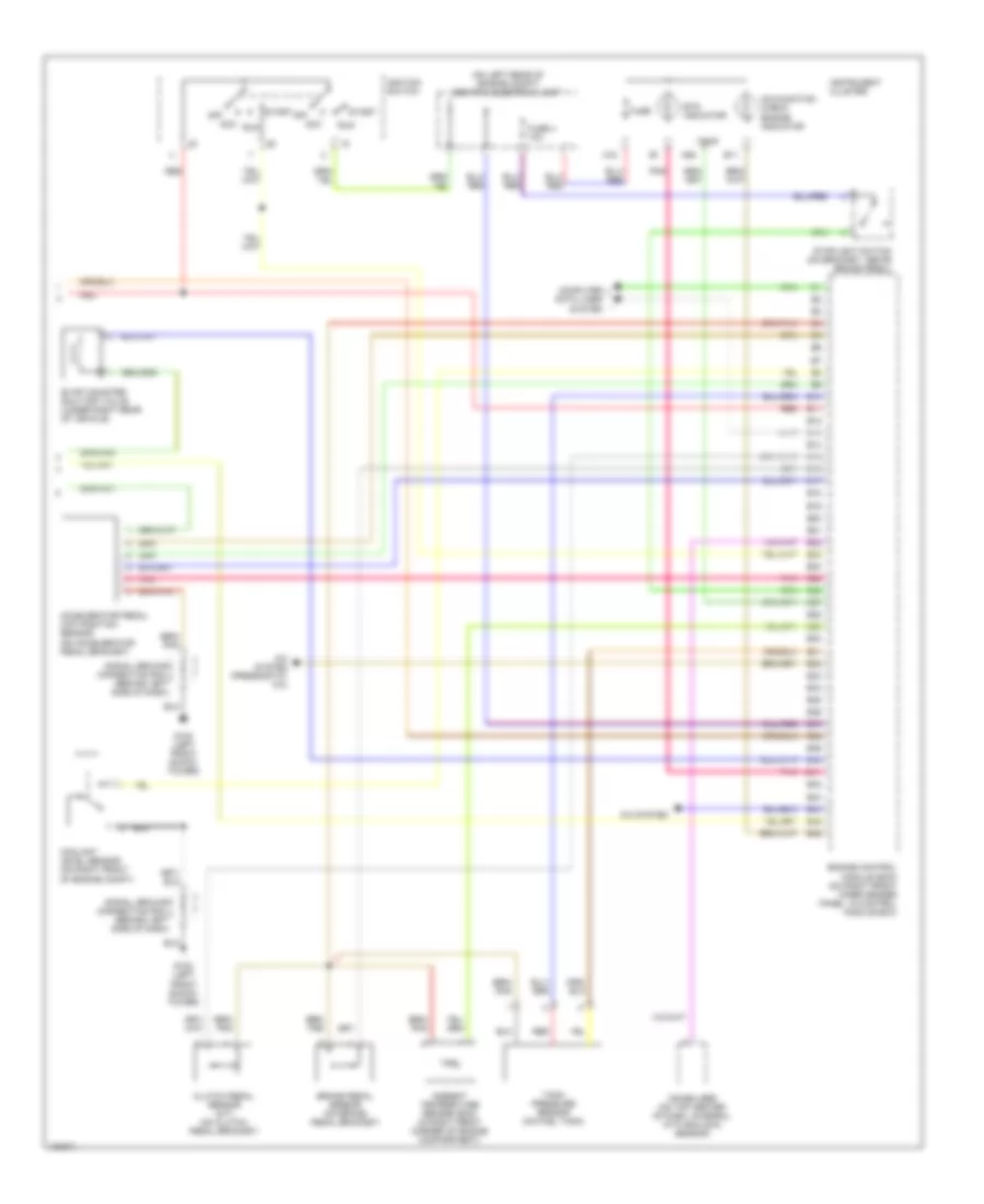
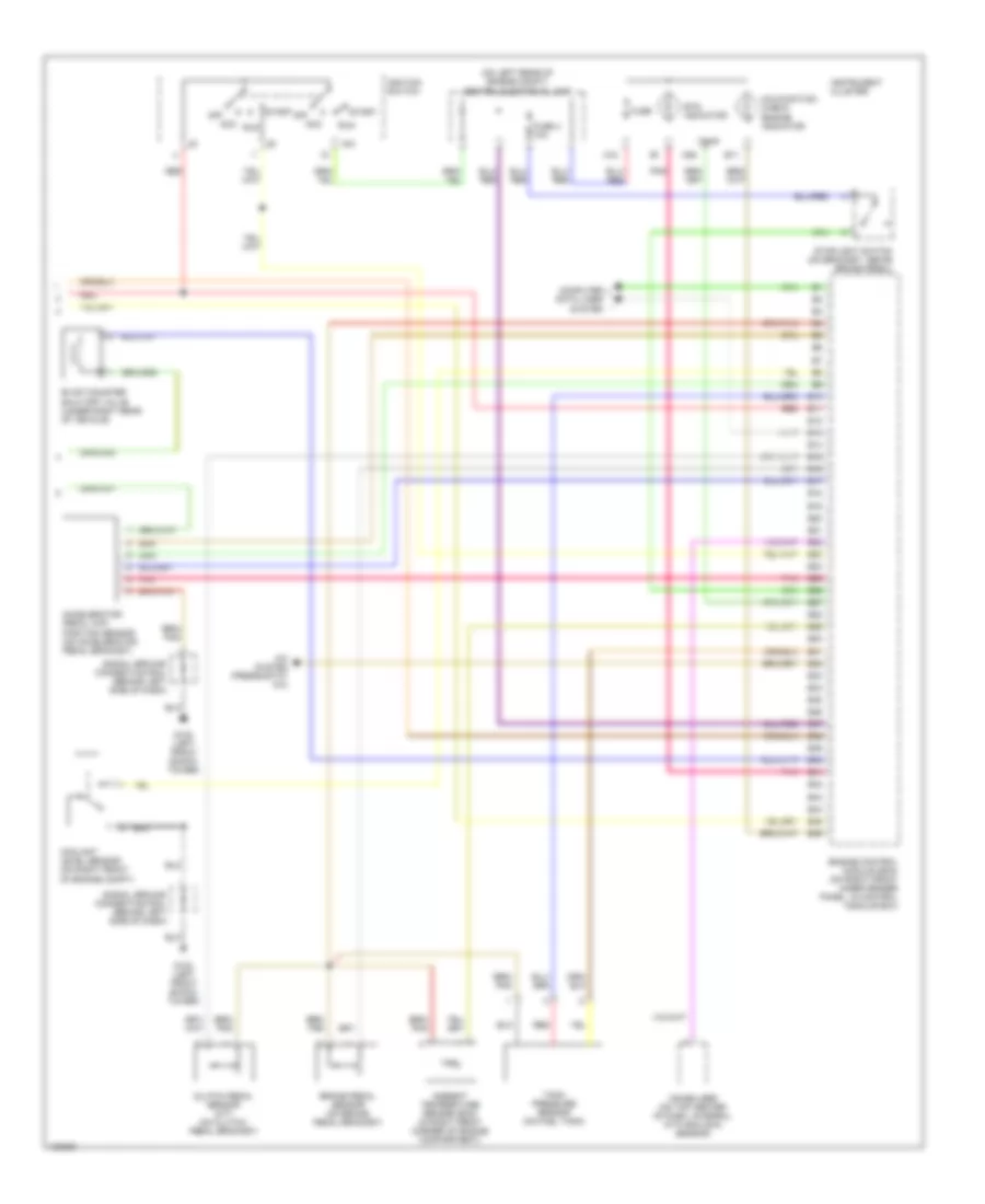
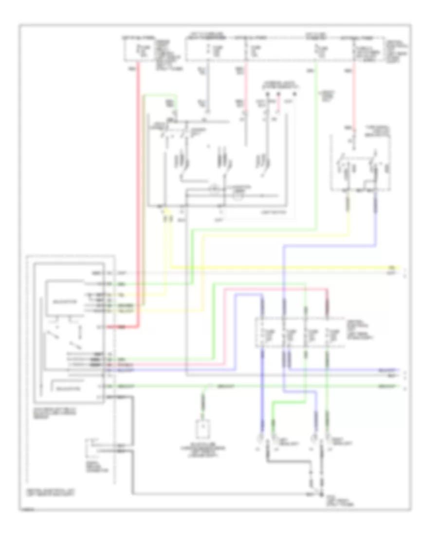
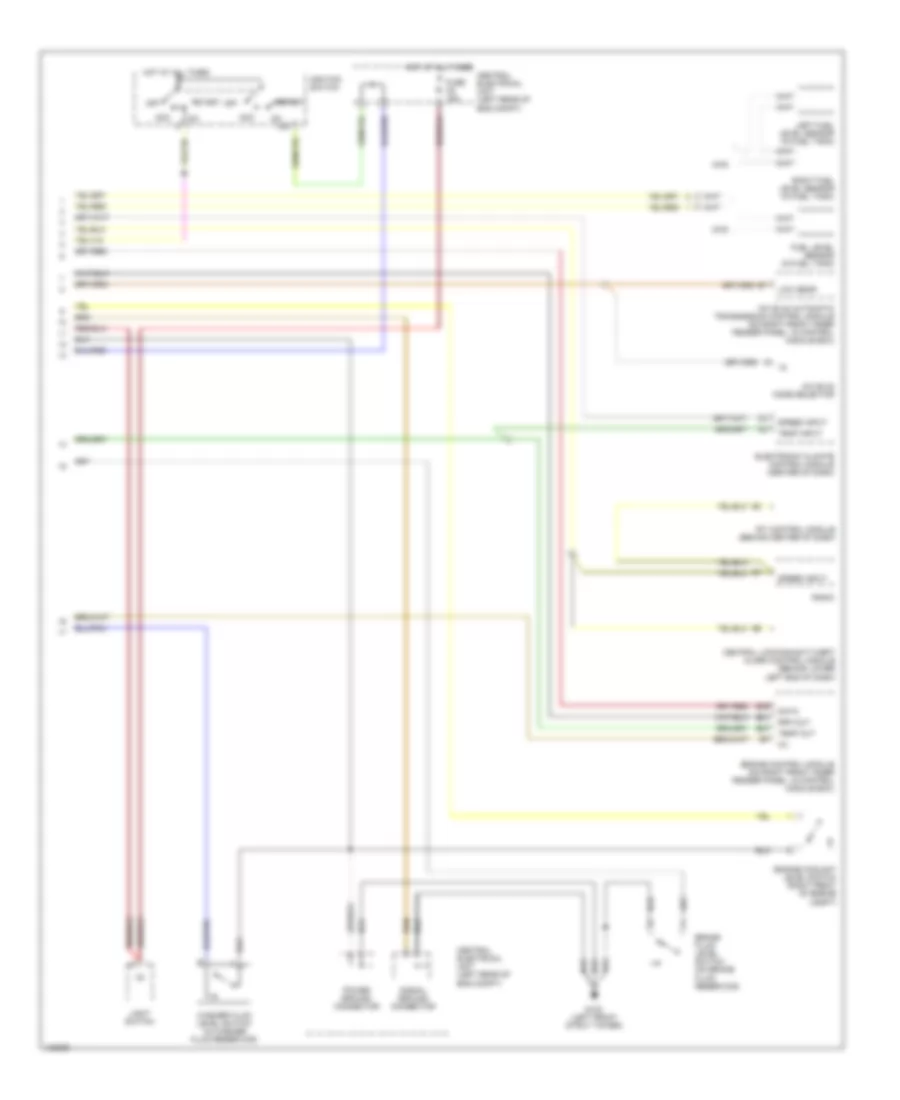
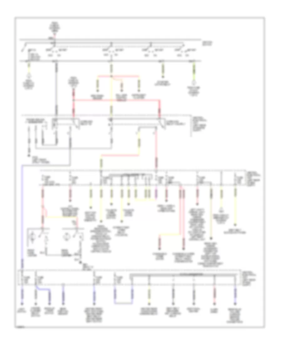
AIR CONDITIONING
2.3L
2.3L Turbo, Manual A/C Wiring Diagram for Volvo V70 T-5 1999
List of elements for 2.3L Turbo, Manual A/C Wiring Diagram for Volvo V70 T-5 1999:
- (not used)
- (on center console, near shift lever)
- (rear of right front fender) g105
- 87a
- A/c press sw
- A/c pressure sensor (on right front of engine compartment)
- A/c pressure switch (pressostat) (on right rear of engine compartment)
- A/c relay (on engine compartment relay/fuse box, position n0 4)
- A/c switch solenoid (on a/c compressor)
- A39
- A60
- A68
- Alternative model
- B10
- B11
- B12
- B13
- B14
- B15
- B16
- B17
- B18
- B19
- B20
- B21
- B22
- B32
- B44
- Base model
- Battery
- Blower fan (behind right side of dash, on hvac housing)
- Blower fan resistor (on right side of hvac housing)
- C2 red
- Central electrical unit (on left rear of engine compartment)
- Climate control system
- Conn a
- Conn b
- Data link connector (dlc)
- Engine compartment relay/fuse box (on left rear of engine compartment, next to strut tower)
- Engine control module (on right front inner fender panel, in control module box)
- Engine coolant (fc) fan (behind radiator)
- Engine coolant fan (fc) relay (on top right of radiator shroud)
- Engine coolant temperature (ect) sensor (on left front of engine)
- Floor, defroster & ventilation shutter servo motor (on left side of hvac housing)
- Fuse 15a
- Fuse 2 15a, (or fuse 5 20a)
- Fuse 25a
- Fuse 60a
- G110 (lower left front of engine)
- Hot at all times
- Hot in acc or on
- Hot in on or start
- Ignition
- Illum
- Interior lights system (rheostat)
- Mode ctrl
- Out1
- Out2
- Pnk
- Rec ctrl
- Recirculation shutter servo motor (on right side of hvac housing)
- Red
- Solid state
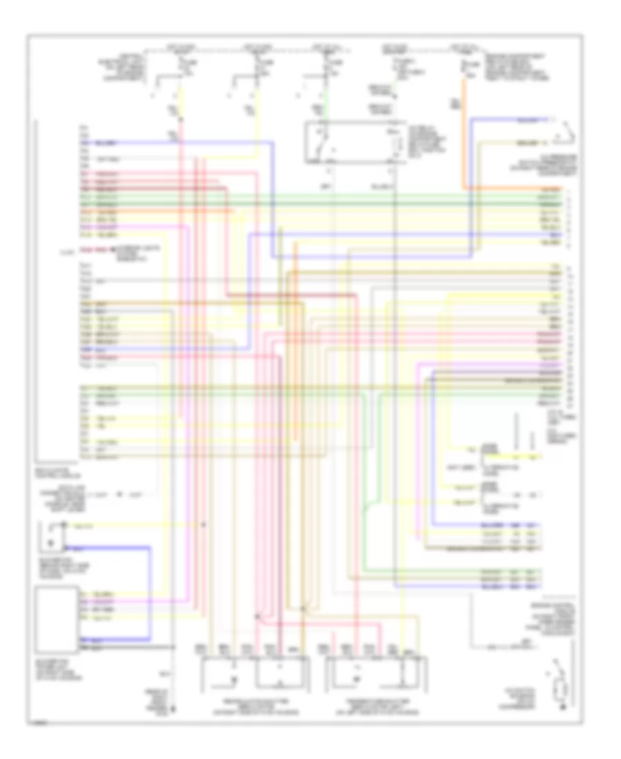
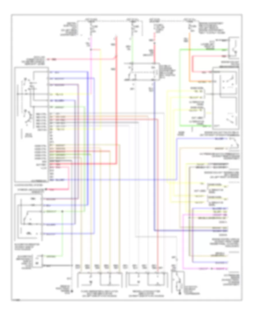
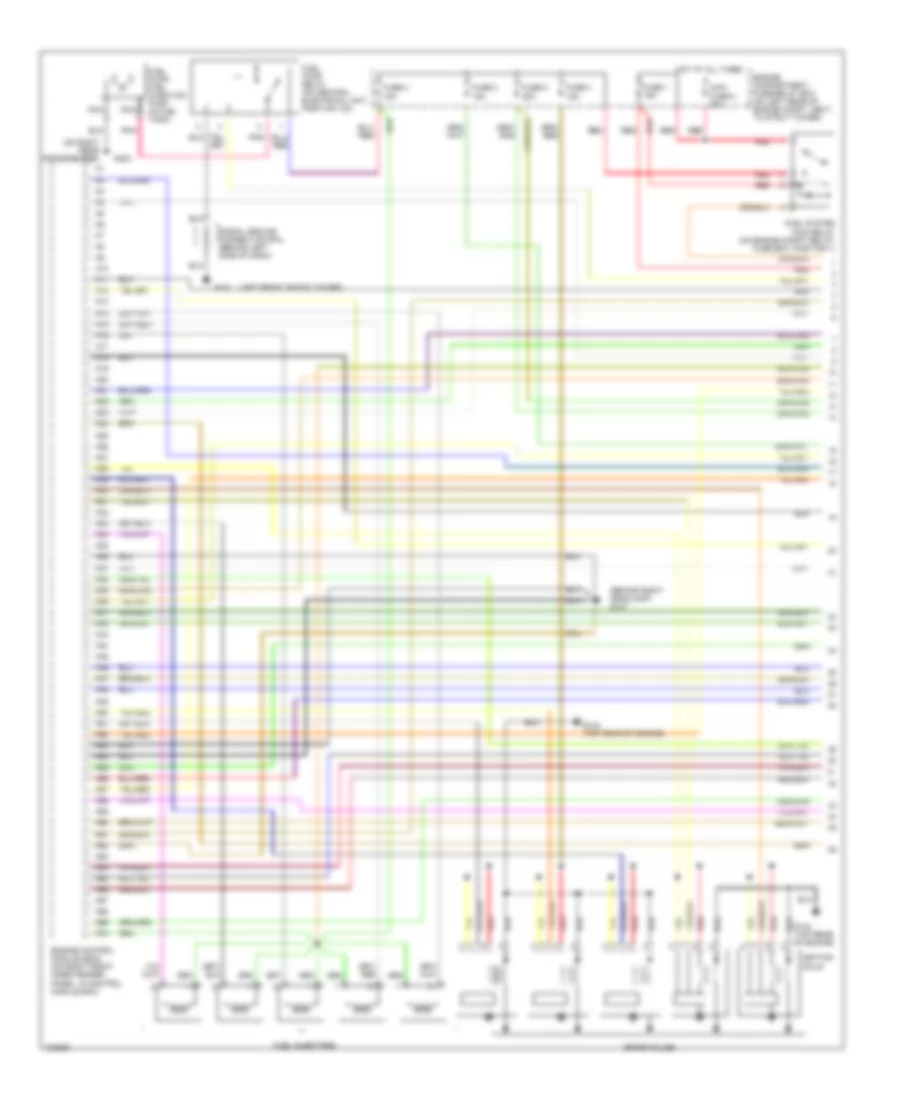
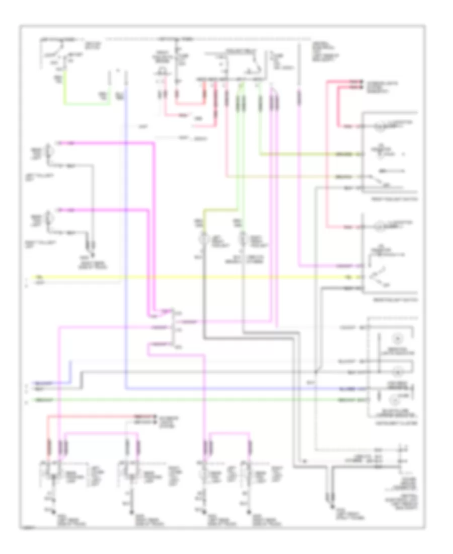
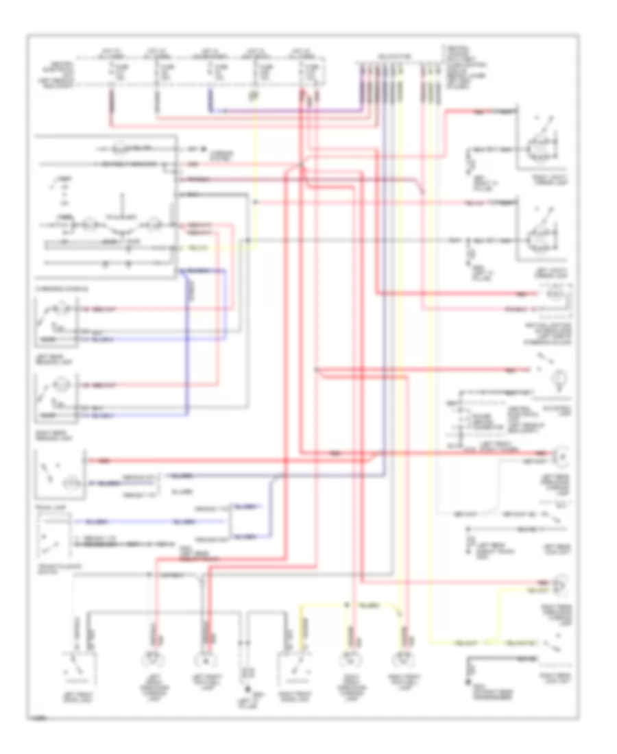
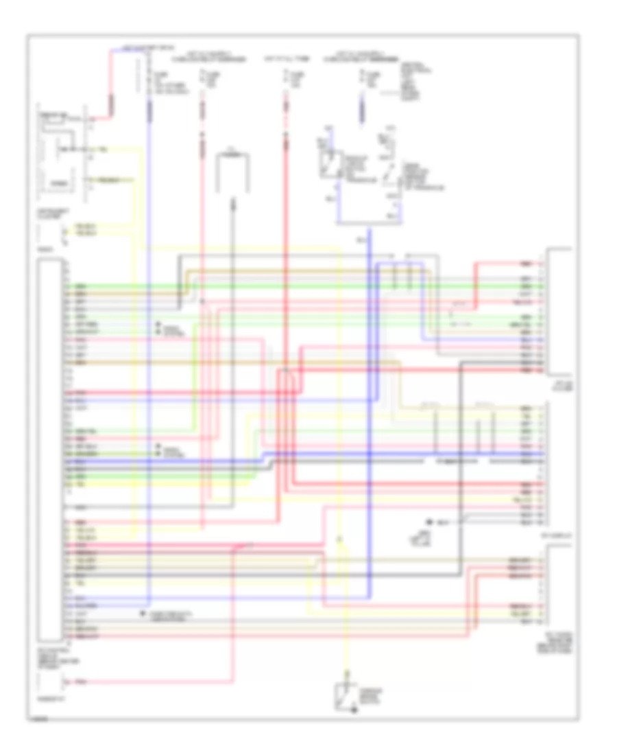
Automatic A/C Wiring Diagram (1 of 2) for Volvo V70 T-5 1999
List of elements for Automatic A/C Wiring Diagram (1 of 2) for Volvo V70 T-5 1999:
- (not used)
- (rear of right front fender) g105
- 2.3l & 2.4l turbo (me7)
- 2.4l non-turbo (denso)
- 87a
- A/c pressure switch (pressostat) (on right rear of engine compartment)
- A/c relay (on engine compartment relay/fuse box, position no 4)
- A/c switch solenoid (on a/c compressor)
- A10
- A11
- A12
- A13
- A14
- A15
- A16
- A17
- A18
- A19
- A20
- A21
- A22
- A23
- A24
- A25
- A26
- A27
- A28
- A29
- A30
- A39
- A40
- A58
- A60
- A61
- A68
- Alternative model
- B27
- B32
- B44
- Base model
- Blower fan (behind right side of dash, on hvac housing)
- Blower fan power unit (on right side of hvac housing)
- C10
- Central electrical unit (on left rear of engine compartment)
- Data link connector (dlc) (on center console, near shift lever)
- Ecc climate control module
- Engine compartment relay/fuse box (on left rear of engine compartment, next to strut tower)
- Engine control module (on right front inner fender panel, in control module box)
- Fuse 10a
- Fuse 15a
- Fuse 2 15a (or fuse 5 20a)
- Fuse 25a
- Fuse 60a
- Hot at all times
- Hot in acc or on
- Hot in on or start
- Illum
- Interior lights system (rheostat)
- Pnk
- Recirculation shutter servo motor (on right side of hvac housing)
- Temperature shutter servo motor (left) (on left side of hvac housing)
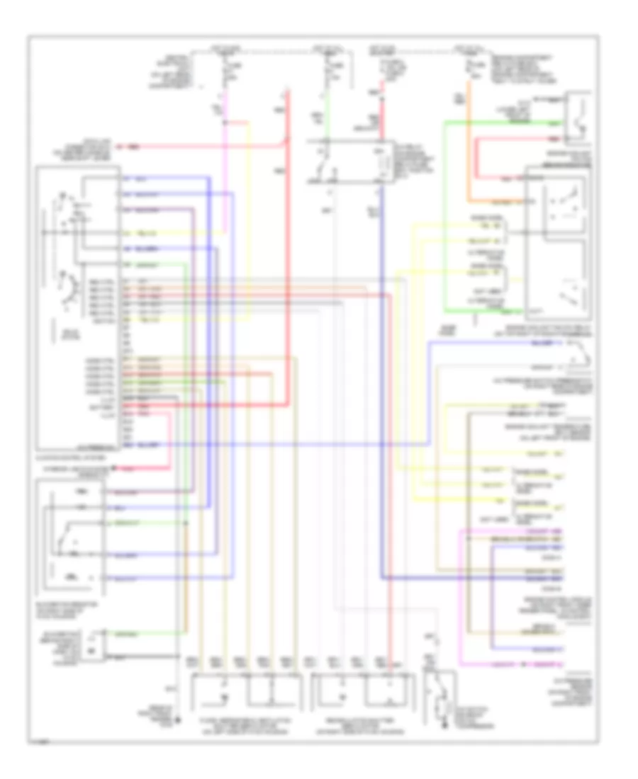
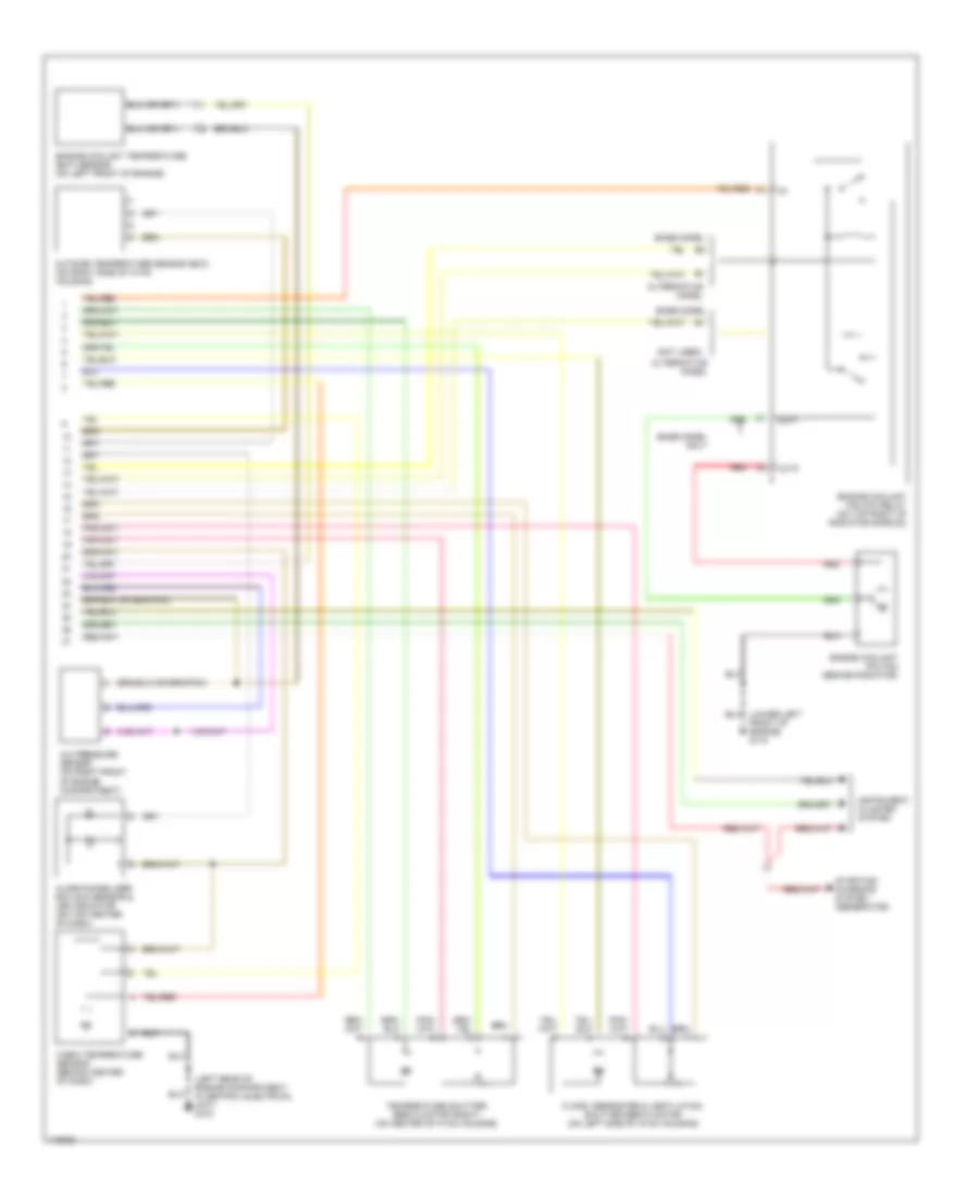
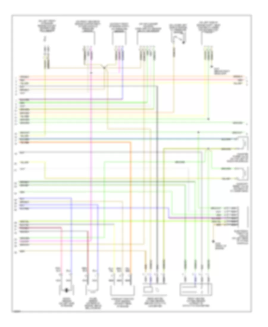
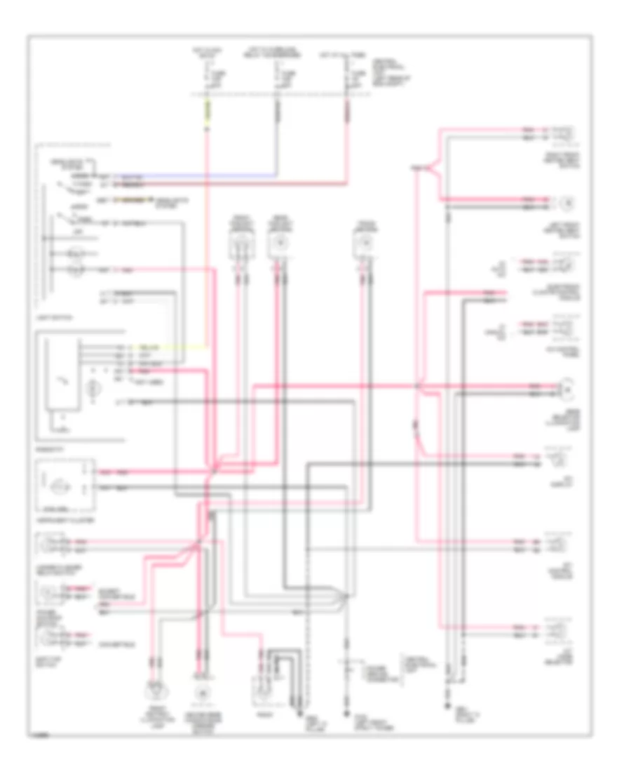
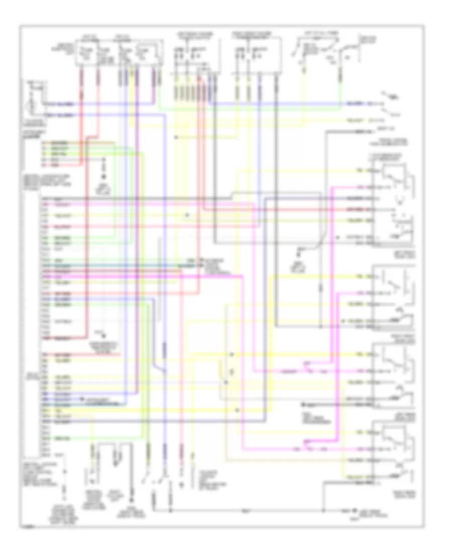
Automatic A/C Wiring Diagram (2 of 2) for Volvo V70 T-5 1999
List of elements for Automatic A/C Wiring Diagram (2 of 2) for Volvo V70 T-5 1999:
- (left rear of engine compartment, in central electrical unit) g104
- (not used)
- A/c pressure sensor (on right front of engine compartment)
- Alarm/immobilizer ecc sun sensor & led indicator (on top center of dash)
- Alternative model
- Base model
- Base model only
- Cabin temperature sensor (behind center of dash)
- Engine coolant (fc) fan (behind radiator)
- Engine coolant fan (fc) relay (on top right of radiator shroud)
- Engine coolant temperature (ect) sensor (on left front of engine)
- Floor, defroster & ventilation shutter servo motor (on left side of hvac housing)
- Front of engine) g110
- Instrument cluster system
- Out1
- Out2
- Outside temperature sensor (ecc) (on right side of hvac housing)
- Red
- Starting/ charging system (generator)
- Temperature shutter servo motor (right) (on center of hvac housing)
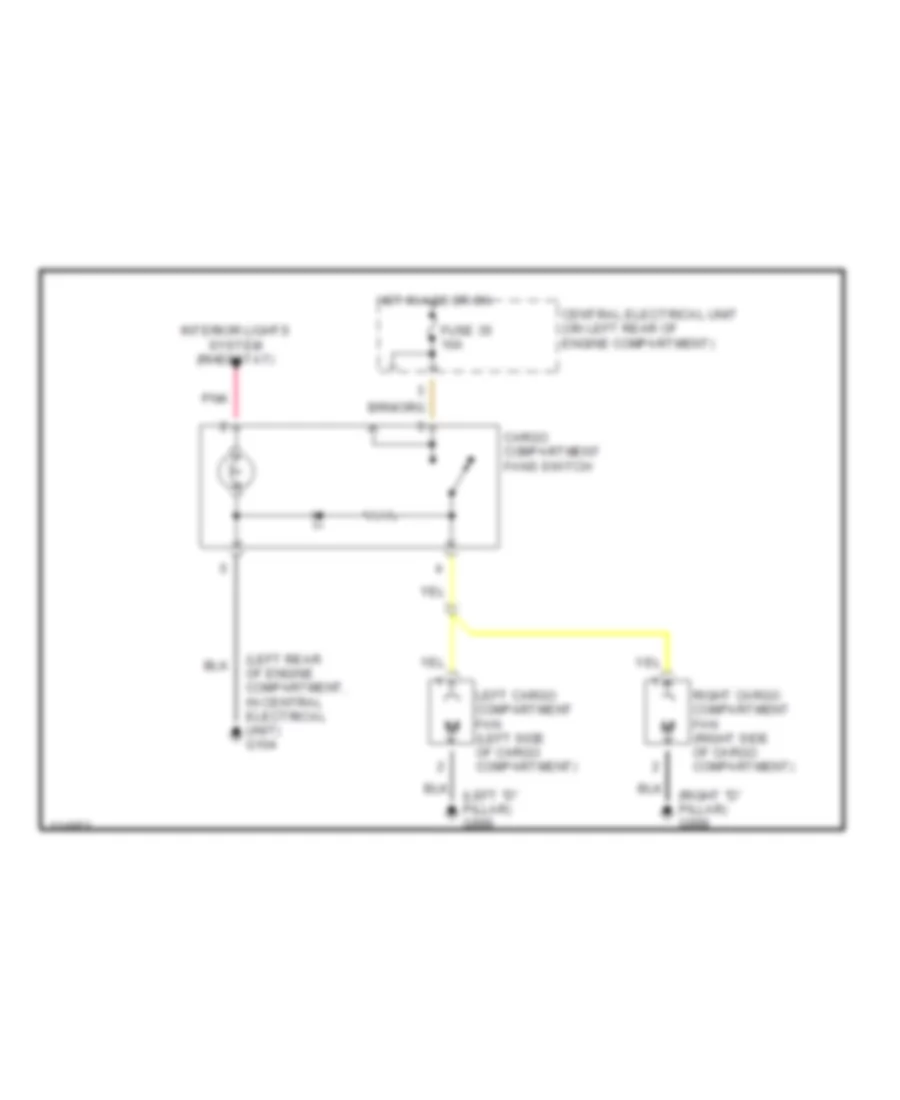
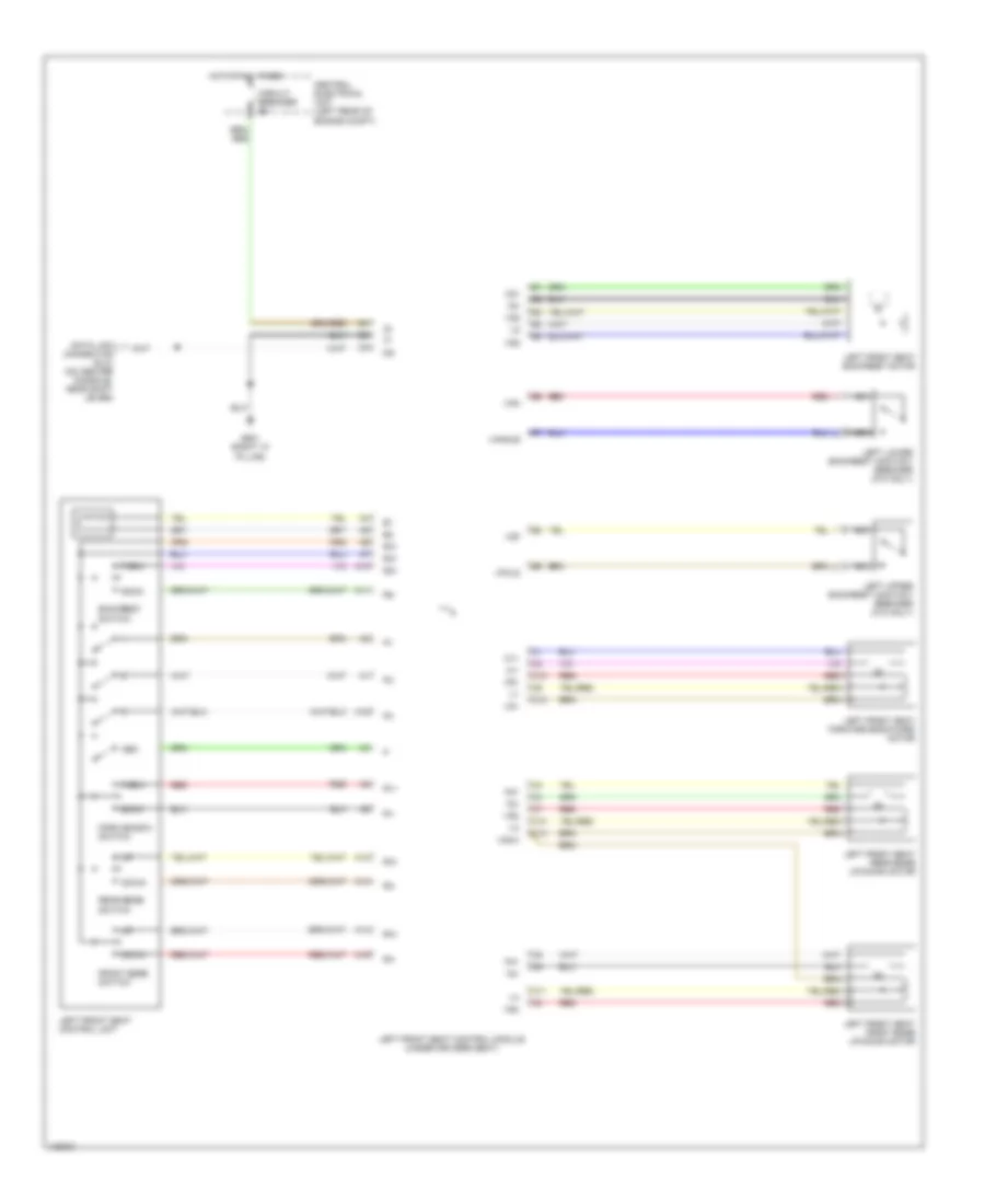
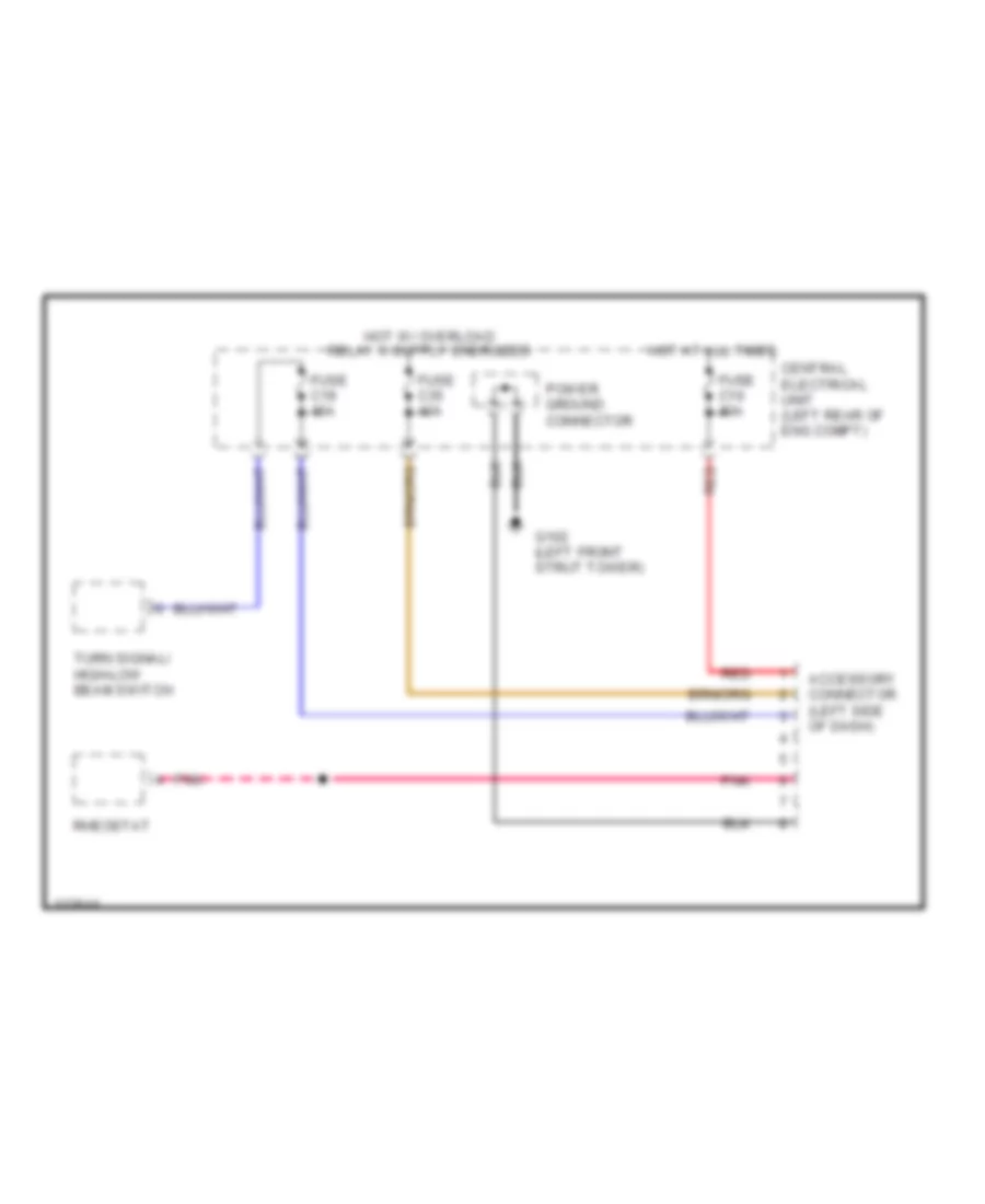
Cargo Compartment Fans Wiring Diagram for Volvo V70 T-5 1999
List of elements for Cargo Compartment Fans Wiring Diagram for Volvo V70 T-5 1999:
- (left "d" pillar) g999
- (left rear of engine compartment, in central electrical unit) g104
- (right "d" pillar) g998
- Cargo compartment fans switch
- Central electrical unit (on left rear of engine compartment)
- Fuse 35 10a
- Hot in acc or on
- Interior lights system (rheostat)
- Left cargo compartment fan (left side of cargo compartment)
- Pnk
- Right cargo compartment fan (right side of cargo compartment)
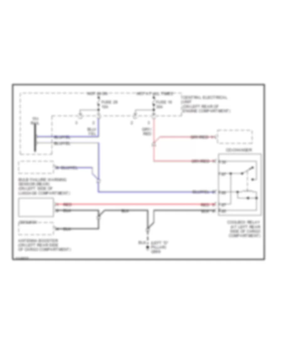
Cool Box Wiring Diagram for Volvo V70 T-5 1999
List of elements for Cool Box Wiring Diagram for Volvo V70 T-5 1999:
- 15-i rail
- Antenna booster (on left rear side of cargo compartment)
- Bulb failure warning sensor (rear) (on left side of luggage compartment)
- Cd-changer
- Central electrical unit (on left rear of engine compartment)
- Coolbox
- Coolbox relay (at left rear side of cargo compartment)
- Fuse 16 30a
- Fuse 29 10a
- Hot at all times
- Hot in on
- Red
2.4L
2.4L Turbo, Manual A/C Wiring Diagram for Volvo V70 T-5 1999
List of elements for 2.4L Turbo, Manual A/C Wiring Diagram for Volvo V70 T-5 1999:
- (not used)
- (on center console, near shift lever)
- (rear of right front fender) g105
- 87a
- A/c press sw
- A/c pressure sensor (on right front of engine compartment)
- A/c pressure switch (pressostat) (on right rear of engine compartment)
- A/c relay (on engine compartment relay/fuse box, position n0 4)
- A/c switch solenoid (on a/c compressor)
- A39
- A60
- A68
- Alternative model
- B10
- B11
- B12
- B13
- B14
- B15
- B16
- B17
- B18
- B19
- B20
- B21
- B22
- B32
- B44
- Base model
- Battery
- Blower fan (behind right side of dash, on hvac housing)
- Blower fan resistor (on right side of hvac housing)
- C2 red
- Central electrical unit (on left rear of engine compartment)
- Climate control system
- Conn a
- Conn b
- Data link connector (dlc)
- Engine compartment relay/fuse box (on left rear of engine compartment, next to strut tower)
- Engine control module (on right front inner fender panel, in control module box)
- Engine coolant (fc) fan (behind radiator)
- Engine coolant fan (fc) relay (on top right of radiator shroud)
- Engine coolant temperature (ect) sensor (on left front of engine)
- Floor, defroster & ventilation shutter servo motor (on left side of hvac housing)
- Fuse 15a
- Fuse 2 15a, (or fuse 5 20a)
- Fuse 25a
- Fuse 60a
- G110 (lower left front of engine)
- Hot at all times
- Hot in acc or on
- Hot in on or start
- Ignition
- Illum
- Interior lights system (rheostat)
- Mode ctrl
- Out1
- Out2
- Pnk
- Rec ctrl
- Recirculation shutter servo motor (on right side of hvac housing)
- Red
- Solid state
2.4L, Manual A/C Wiring Diagram for Volvo V70 T-5 1999
List of elements for 2.4L, Manual A/C Wiring Diagram for Volvo V70 T-5 1999:
- (not used)
- (on center console, near shift lever)
- (rear of right front fender) g105
- 87a
- A/c press sw
- A/c pressure sensor (on right front of engine compartment)
- A/c pressure switch (pressostat) (on right rear of engine compartment)
- A/c relay (on engine compartment relay/fuse box, position n0 4)
- A/c switch solenoid (on a/c compressor)
- A21
- A40
- A58
- A61
- Alternative model
- B10
- B11
- B12
- B13
- B14
- B15
- B16
- B17
- B18
- B19
- B20
- B21
- B22
- B32
- B44
- Base model
- Battery
- Blower fan (behind right side of dash, on hvac housing)
- Blower fan resistor (on right side of hvac housing)
- C2 red
- Central electrical unit (on left rear of engine compartment)
- Climate control system
- Conn a
- Conn b
- Data link connector (dlc)
- Engine compartment relay/fuse box (on left rear of engine compartment, next to strut tower)
- Engine control module (on right front inner fender panel, in control module box)
- Engine coolant (fc) fan (behind radiator)
- Engine coolant fan (fc) relay (on top right of radiator shroud)
- Engine coolant temperature (ect) sensor (on left front of engine)
- Floor, defroster & ventilation shutter servo motor (on left side of hvac housing)
- Fuse 15a
- Fuse 2 15a, (or fuse 5 20a)
- Fuse 25a
- Fuse 60a
- G110 (lower left front of engine)
- Gnd
- Hot at all times
- Hot in acc or on
- Hot in on or start
- Ignition
- Illum
- Interior lights system (rheostat)
- Mode ctrl
- Out1
- Out2
- Pnk
- Rec ctrl
- Recirculation shutter servo motor (on right side of hvac housing)
- Red
- Solid state
Automatic A/C Wiring Diagram (1 of 2) for Volvo V70 T-5 1999
List of elements for Automatic A/C Wiring Diagram (1 of 2) for Volvo V70 T-5 1999:
- (not used)
- (rear of right front fender) g105
- 2.3l & 2.4l turbo (me7)
- 2.4l non-turbo (denso)
- 87a
- A/c pressure switch (pressostat) (on right rear of engine compartment)
- A/c relay (on engine compartment relay/fuse box, position no 4)
- A/c switch solenoid (on a/c compressor)
- A10
- A11
- A12
- A13
- A14
- A15
- A16
- A17
- A18
- A19
- A20
- A21
- A22
- A23
- A24
- A25
- A26
- A27
- A28
- A29
- A30
- A39
- A40
- A58
- A60
- A61
- A68
- Alternative model
- B27
- B32
- B44
- Base model
- Blower fan (behind right side of dash, on hvac housing)
- Blower fan power unit (on right side of hvac housing)
- C10
- Central electrical unit (on left rear of engine compartment)
- Data link connector (dlc) (on center console, near shift lever)
- Ecc climate control module
- Engine compartment relay/fuse box (on left rear of engine compartment, next to strut tower)
- Engine control module (on right front inner fender panel, in control module box)
- Fuse 10a
- Fuse 15a
- Fuse 2 15a (or fuse 5 20a)
- Fuse 25a
- Fuse 60a
- Hot at all times
- Hot in acc or on
- Hot in on or start
- Illum
- Interior lights system (rheostat)
- Pnk
- Recirculation shutter servo motor (on right side of hvac housing)
- Temperature shutter servo motor (left) (on left side of hvac housing)
Automatic A/C Wiring Diagram (2 of 2) for Volvo V70 T-5 1999
List of elements for Automatic A/C Wiring Diagram (2 of 2) for Volvo V70 T-5 1999:
- (left rear of engine compartment, in central electrical unit) g104
- (not used)
- A/c pressure sensor (on right front of engine compartment)
- Alarm/immobilizer ecc sun sensor & led indicator (on top center of dash)
- Alternative model
- Base model
- Base model only
- Cabin temperature sensor (behind center of dash)
- Engine coolant (fc) fan (behind radiator)
- Engine coolant fan (fc) relay (on top right of radiator shroud)
- Engine coolant temperature (ect) sensor (on left front of engine)
- Floor, defroster & ventilation shutter servo motor (on left side of hvac housing)
- Front of engine) g110
- Instrument cluster system
- Out1
- Out2
- Outside temperature sensor (ecc) (on right side of hvac housing)
- Red
- Starting/ charging system (generator)
- Temperature shutter servo motor (right) (on center of hvac housing)
Cargo Compartment Fans Wiring Diagram for Volvo V70 T-5 1999
List of elements for Cargo Compartment Fans Wiring Diagram for Volvo V70 T-5 1999:
- (left "d" pillar) g999
- (left rear of engine compartment, in central electrical unit) g104
- (right "d" pillar) g998
- Cargo compartment fans switch
- Central electrical unit (on left rear of engine compartment)
- Fuse 35 10a
- Hot in acc or on
- Interior lights system (rheostat)
- Left cargo compartment fan (left side of cargo compartment)
- Pnk
- Right cargo compartment fan (right side of cargo compartment)
Cool Box Wiring Diagram for Volvo V70 T-5 1999
List of elements for Cool Box Wiring Diagram for Volvo V70 T-5 1999:
- 15-i rail
- Antenna booster (on left rear side of cargo compartment)
- Bulb failure warning sensor (rear) (on left side of luggage compartment)
- Cd-changer
- Central electrical unit (on left rear of engine compartment)
- Coolbox
- Coolbox relay (at left rear side of cargo compartment)
- Fuse 16 30a
- Fuse 29 10a
- Hot at all times
- Hot in on
- Red
ANTI-LOCK BRAKES
Anti-lock Brake Wiring Diagrams for Volvo V70 T-5 1999
List of elements for Anti-lock Brake Wiring Diagrams for Volvo V70 T-5 1999:
- (1999)
- 15a
- A15
- A18
- A19
- A20
- A28
- A29
- A37
- A55
- Abs control module (on left rear of engine compt)
- Abs pump motor
- Acc
- B13
- B16
- B30
- Brake fluid level sensor (in brake master cylinder reservoir)
- Brake fluid level warning indicator
- Brake pedal switch
- Cdm
- Central electrical unit (left rear of engine compt)
- Computer data lines system (diesel w/ a/t)
- Computer data lines system (except diesel)
- Cpu
- Data link connector (center console, near shift lever)
- Engine compartment relay/fuse box (left rear of engine compt)
- Engine control module (on right front inner fender panel)
- Fuse
- Fuse a4 50a
- Fuse c11 10a
- Fuse c4 10a
- G102 (left front shock tower)
- G102 (left front strut tower)
- Gasoline engines w/ m/t
- Hot at all times
- Ignition switch
- Illum- ination lamp
- Instrument cluster
- Interior lights system
- Left front abs sensor (on wheel hub)
- Left rear abs sensor (on wheel hub)
- Nca
- Off
- Parking brake on indicator
- Parking brake switch
- Pnk
- Red
- Right front abs sensor (on wheel hub)
- Right rear abs sensor (on wheel hub)
- Signal ground connector
- Start
- Tracs on indicator
- Tracs switch
ANTI-THEFT
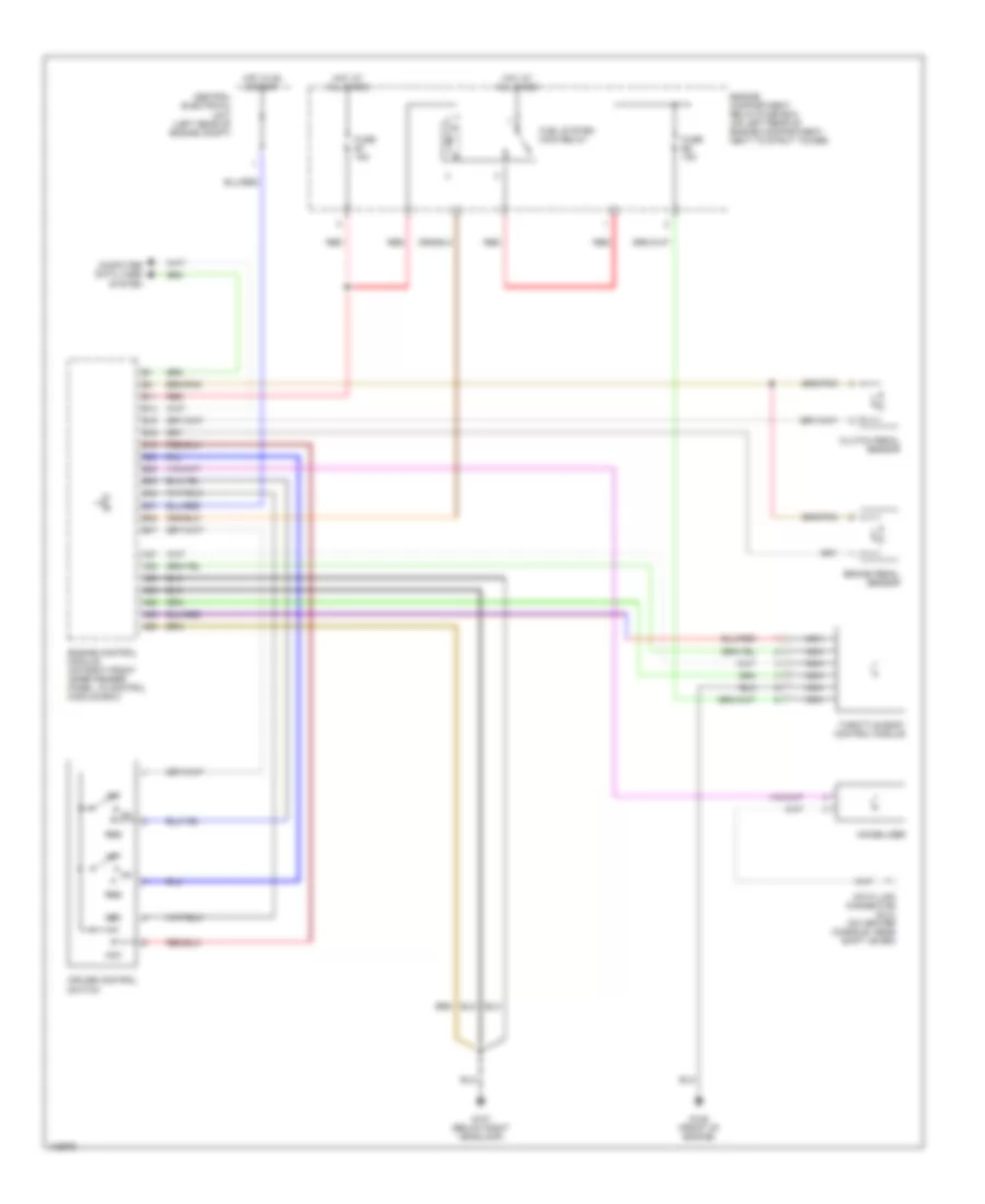
Anti-theft Alarm Wiring Diagram for Volvo V70 T-5 1999
List of elements for Anti-theft Alarm Wiring Diagram for Volvo V70 T-5 1999:
- (right "a" pillar)
- (right side of engine compt)
- 15i-rail connector
- A/c system
- A10
- A11
- A12
- A13
- A14
- A15
- A16
- A17
- A18
- A19
- A20
- A21
- A22
- A23
- A24
- A25
- A26
- Alarm horn (rear center of engine compt)
- Alarm horn relay (on central electrical unit, position 202)
- Alarm siren
- Alarm/ electronic immobilizer indicator
- B10
- B11
- B12
- B13
- B14
- B15
- B16
- B17
- B18
- B19
- B20
- B21
- Bonnet alarm switch (front of eng compt)
- C10
- Car tilt sensor (on right rear corner of vehicle)
- Central electrical unit (left rear of engine compt)
- Central locking/ anti-theft alarm control module (behind lower left end of dash)
- Central locking/alarm remote control unit (behind upper left side of dash)
- Circuit
- Data link connector (on center console, near shift lever)
- Door locks system
- Electronic climate control module (behind center of dash)
- Exterior lights system (turn signal)
- Fuse c10 10a
- Fuse c13 15a
- Fuse c18 10a
- Fuse c29 10a
- Fuse c3 10a
- Fuse c6 20a
- G102 (left front strut tower)
- G404 (left rear side of trunk)
- G900 (left "a" pillar)
- G901
- Glass breakage sensor (behind right side of dash)
- Hot at all times
- Hot in on or start
- Hot w/ overload relay 15i energized
- Ignition switch
- Immobilizer
- Instrument cluster system
- Key in ignition switch
- Left movement detector (left "b" pillar)
- Left rear side window alarm lead (v70 only)
- Microphone
- Nca
- Power ground rail (in central electrical unit)
- Rear heated window element
- Red
- Right movement detector (right "b" pillar)
- Right rear side window alarm lead (v70 only)
- Solid state
- Starter motor relay (in eng compt relay/fuse box position 3)
- W/ ecc
- W/o ecc
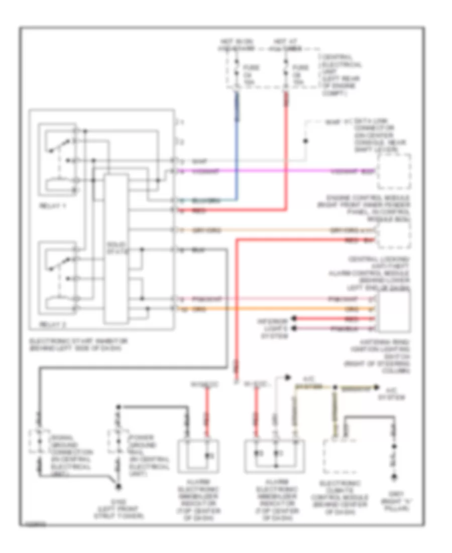
Immobilizer Wiring Diagram for Volvo V70 T-5 1999
List of elements for Immobilizer Wiring Diagram for Volvo V70 T-5 1999:
- A/c system
- A11
- A23
- Alarm/ electronic immobilizer indicator (top center of dash)
- Antenna ring/ ignition lighting switch (right of steering column)
- B22
- C10
- Central electrical unit (left rear of engine compt)
- Central locking/ anti-theft alarm control module (behind lower left end of dash)
- Connector (on center console, near shift lever)
- Data link
- Electronic climate control module (behind center of dash)
- Electronic start inhibitor (behind left side of dash)
- Engine control module (right front inner fender panel, in control module box)
- Fuse c4 10a
- Fuse c8 15a
- G102 (left front strut tower)
- G901 (right "a" pillar)
- Hot at all times
- Hot in on and start
- Interior lights system
- Power ground rail (in central electrical unit)
- Red
- Relay 1
- Relay 2
- Signal ground connection (in central electrical unit)
- Solid state
- W/ ecc
- W/o ecc
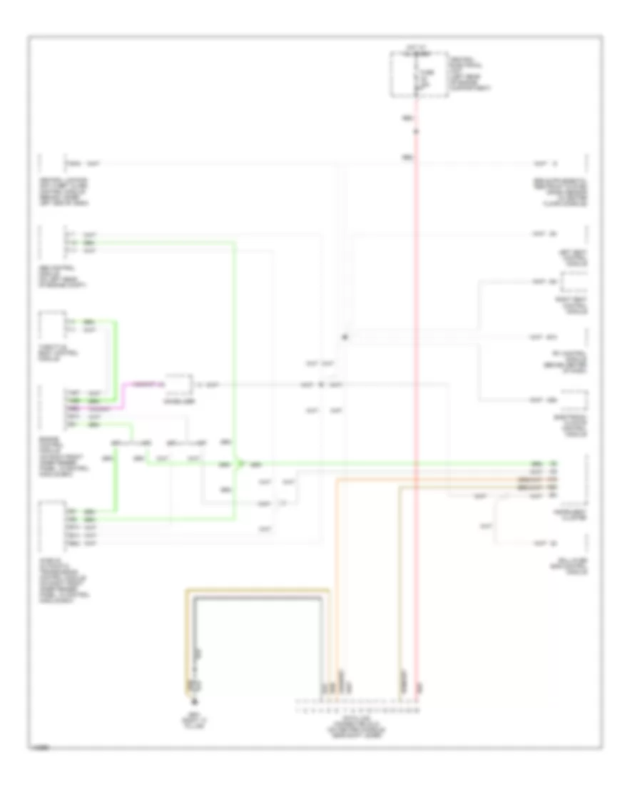
COMPUTER DATA LINES
Computer Data Lines for Volvo V70 T-5 1999
List of elements for Computer Data Lines for Volvo V70 T-5 1999:
- A/t
- A19
- A20
- A30
- A37
- A55
- Abs control module (on left rear of engine compt)
- Aw50-42 automatic transmission control module (on right front inner fender panel, in control module box)
- B13
- B14
- B19
- B22
- Central electrical unit (left rear of engine compartment)
- Central locking/ anti-theft alarm control module (behind lower left end of dash)
- Data link connector (dlc) (on center console, near shift lever)
- Electronic climate control module
- Engine control module (on right front inner fender panel, in control module box)
- Fuse c5 15a
- G901 (right "a" pillar)
- Hot at all times
- Immobilizer
- Instrument cluster
- Left seat control module
- M/t
- Red
- Right seat control module
- Roll-over bar control module
- Rti control module (behind center of dash)
- Throttle body control module
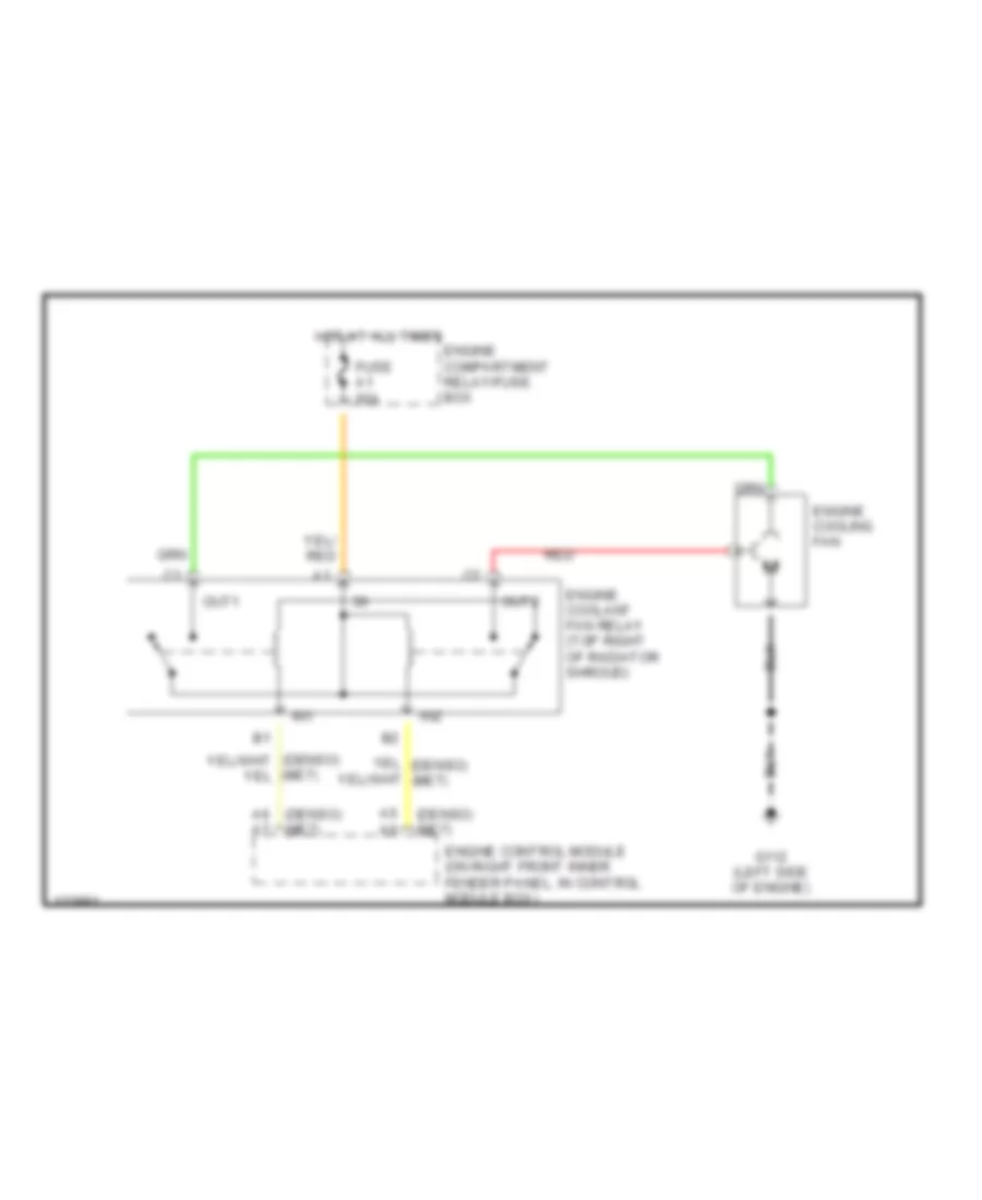
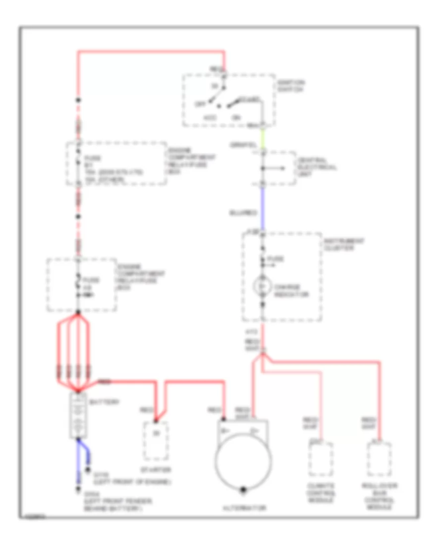
COOLING FAN
Cooling Fan Wiring Diagram for Volvo V70 T-5 1999
List of elements for Cooling Fan Wiring Diagram for Volvo V70 T-5 1999:
- (denso) (me7)
- (denso) a6 a7
- (me7)
- A5 a6
- Engine compartment relay/fuse box
- Engine control module (on right front inner fender panel, in control module box)
- Engine coolant fan relay (top right of radiator shroud)
- Engine cooling fan
- Fuse a1 60a
- G112 (left side of engine)
- Hot at all times
- In1
- In2
- Out1
- Out2
- Red
CRUISE CONTROL
Cruise Control Wiring Diagram for Volvo V70 T-5 1999
List of elements for Cruise Control Wiring Diagram for Volvo V70 T-5 1999:
- A37
- A38
- A53
- A54
- A55
- A56
- A63
- Acc
- B11
- B13
- B15
- B16
- B19
- B20
- B22
- B33
- B34
- B37
- B38
- B47
- Brake pedal sensor
- Central electrical unit (left rear of engine compt)
- Clutch pedal sensor
- Computer data lines system
- Cruise control switch
- Data link connector (dlc) (on center console, near shift lever)
- Dec
- Engine compartment relay/fuse box (on left rear of engine compartment, next to strut tower)
- Engine control module (on right front inner fender panel, in control module box)
- Fuel system main relay
- Fuse b1 15a
- Fuse b2 15a
- G107 (below right headlamp)
- G125 (front of engine)
- Hot at all times
- Hot in on & start
- Immobilizer
- Nca
- Off
- Red
- Res
- Throttle body control module
DEFOGGERS
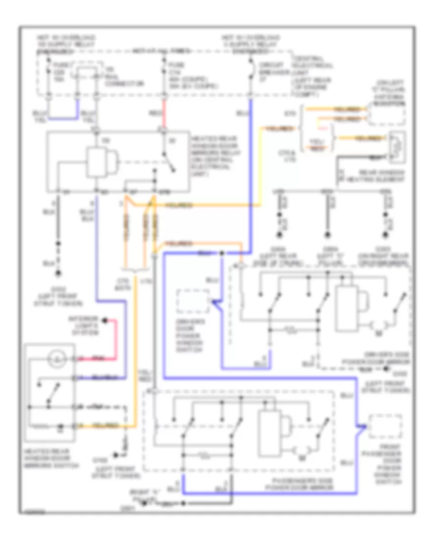
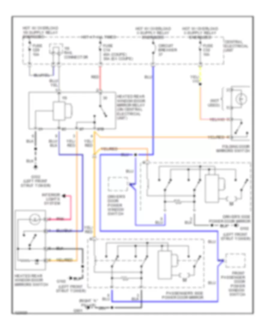
Rear Defogger & Heated Mirrors Wiring Diagram, with Fold-Back Mirrors for Volvo V70 T-5 1999
List of elements for Rear Defogger & Heated Mirrors Wiring Diagram, with Fold-Back Mirrors for Volvo V70 T-5 1999:
- (left front strut tower)
- (on left "c" pillar) antenna booster
- (right "a" pillar)
- 15i
- 15i rail connector
- 87b
- C70
- C70 & v70
- C70 &s70
- Central electrical unit (left rear of engine compt)
- Circuit breaker
- Driver's door power window switch
- Driver's side power door mirror
- Front passenger door power window switch
- Fuse c14 40a (coupe) 30a (ex coupe)
- Fuse c29 10a
- G102
- G102 (left front strut tower)
- G303 (on right rear crossmember)
- G404 (left rear side of trunk)
- G901
- G904 (left "c" pillar)
- Heated rear window/door mirrors relay (on central electrical unit)
- Heated rear window/door mirrors switch
- Hot at all times
- Interior lights system
- Passenger's side power door mirror
- Pnk
- Rear window heating element
- Red
- S70
- V70
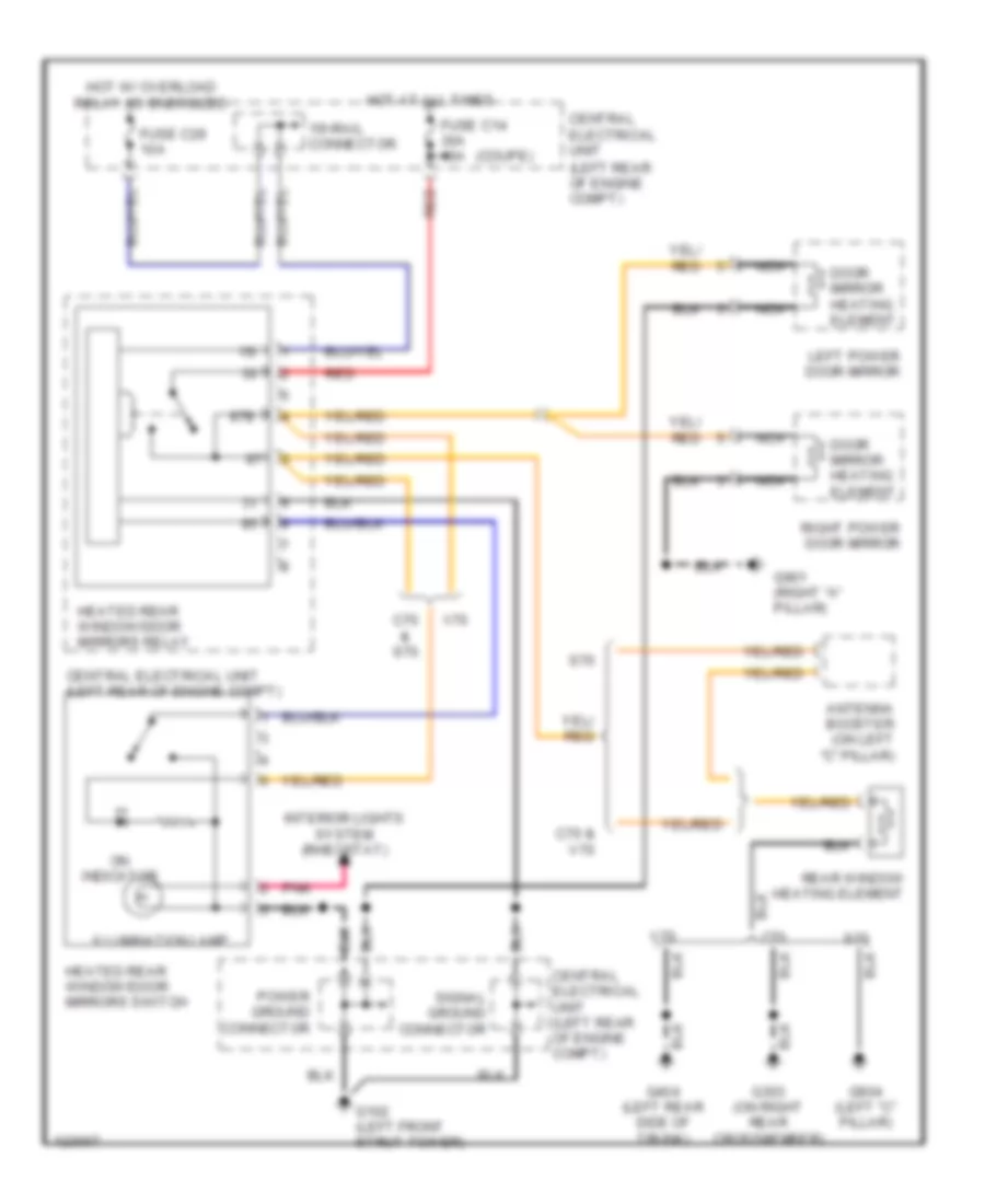
Rear Defogger & Heated Mirrors Wiring Diagram, without Fold-Back Mirrors for Volvo V70 T-5 1999
List of elements for Rear Defogger & Heated Mirrors Wiring Diagram, without Fold-Back Mirrors for Volvo V70 T-5 1999:
- (coupe)
- 15i
- 15i-rail connector
- 87b
- Antenna booster (on left "c" pillar)
- C70 & s70
- C70 & v70
- Central electrical unit (left rear of engine compt)
- Door mirror heating element
- Fuse c14 30a 40a
- Fuse c29 10a
- G102 (left front strut tower)
- G303 (on right rear crossmember)
- G404 (left rear side of trunk)
- G901 (right "a" pillar)
- G904 (left "c" pillar)
- Heated rear window/door mirrors relay
- Heated rear window/door mirrors switch
- Hot at all times
- Hot w/ overload relay 15i energized
- Illumination lamp
- Interior lights system (rheostat)
- Left power door mirror
- Nca
- On indicator
- Pnk
- Power ground connector
- Rear window heating element
- Red
- Right power door mirror
- S70
- Signal ground connector
- V70
ENGINE PERFORMANCE
2.3L
2.3L Turbo, Engine Performance Wiring Diagrams (1 of 3) for Volvo V70 T-5 1999
List of elements for 2.3L Turbo, Engine Performance Wiring Diagrams (1 of 3) for Volvo V70 T-5 1999:
- (behind right headlamp) g107
- (left front shock tower)
- (on right rear crossmember)
- A10
- A11
- A12
- A13
- A14
- A15
- A16
- A17
- A18
- A19
- A20
- A21
- A22
- A23
- A24
- A25
- A26
- A27
- A28
- A29
- A30
- A31
- A32
- A33
- A34
- A35
- A36
- A37
- A38
- A39
- A40
- A41
- A42
- A43
- A44
- A45
- A46
- A47
- A48
- A49
- A50
- A51
- A52
- A53
- A54
- A55
- A56
- A57
- A58
- A59
- A60
- A61
- A62
- A63
- A64
- A65
- A66
- A67
- A68
- A69
- A70
- Cooling fans system
- Engine compartment fuse/relay box (on left rear of engine compt, next to strut tower)
- Engine control module (ecm) (on right front inner fender panel, in control module box)
- Fuel injectors
- Fuel pump relay (on central electrical unit, position 103)
- Fuel pump/ fuel injection pump (in fuel tank)
- Fuel system main relay (on engine compt relay/ fuse box, position 1)
- Fuse 1 15a
- Fuse 2 15a
- Fuse 3 15a
- Fuse 4 15a
- Fuse 5 20a
- G102
- G134 (top rear of engine)
- G303
- Hot at all times
- Ignition coils
- Maxi fuse 8 60a
- Nca
- Pnk
- Red
- Signal ground connection rail (behind left side of dash)
- Spark plugs
2.3L Turbo, Engine Performance Wiring Diagrams (2 of 3) for Volvo V70 T-5 1999
List of elements for 2.3L Turbo, Engine Performance Wiring Diagrams (2 of 3) for Volvo V70 T-5 1999:
- (in intake air hose, near air cleaner) intake air temperature (iat) sensor
- (on air cleaner housing) mass airflow sensor/ air volume sensor
- (on front center of engine compartment) intake manifold pressure sensor
- (on left front of engine) engine coolant temperature (ect) sensor
- (on lower left side of engine) oil pressure sensor
- (on rear of engine) turbocharger control valve
- (on right front of engine compt) a/c pressure sensor
- Camshaft position (cmp) sensor (on right rear of engine)
- Camshaft reset valve (on front of cylinder head)
- Canister purge valve (on top left of radiator shroud)
- Electronic throttle module (on left rear of intake manifold)
- Front heated oxygen sensor (in front of catalytic converter)
- Front knock sensor (on left side of engine)
- G125 (front of engine)
- G134 (top rear of engine)
- Nca
- Nca nca
- Ptc air preheating resistor
- Pulse sensor (on rear of engine, above bellhousing)
- Rear heated oxygen sensor (behind catalytic converter)
- Rear knock sensor (on left side of engine)
- Red
2.3L Turbo, Engine Performance Wiring Diagrams (3 of 3) for Volvo V70 T-5 1999
List of elements for 2.3L Turbo, Engine Performance Wiring Diagrams (3 of 3) for Volvo V70 T-5 1999:
- (on left rear of engine compt) central electrical unit
- A/c system
- A/c system (pressostat a/c)
- A18
- A26
- Acc
- Accelerator pedal (a/p) position sensor (on accelerator pedal bracket)
- Ambient temperature sensor (ecm) (in right front corner of engine compartment)
- B10
- B11
- B12
- B13
- B14
- B15
- B16
- B17
- B18
- B19
- B20
- B21
- B22
- B23
- B24
- B25
- B26
- B27
- B28
- B29
- B30
- B31
- B32
- B33
- B34
- B35
- B36
- B37
- B38
- B39
- B40
- B41
- B42
- B43
- B44
- B45
- B46
- Brake pedal sensor (on brake pedal bracket)
- Clutch pedal sensor (m/t) (on clutch pedal bracket)
- Computer data lines system
- Coolant level sensor (on right front of engine compt)
- Engine control module (ecm) (on right front inner fender panel, in control module box)
- Ets indicator
- Evap canister shut-off valve (under right rear of vehicle)
- Fuse
- Fuse 4 10a
- G102 (left front shock tower)
- Ignition switch
- Immobilizer (on top center of dash, integral with ecc sun sensor)
- Instrument cluster
- Malfunction check engine indicator
- Off
- Pnk
- Red
- Run
- Signal ground connection rail (behind left side of dash)
- Start
- Stoplight switch (on bracket, above brake pedal)
- Tank pressure sensor (on fuel tank)
- Temp
2.4L
2.4L Turbo, Engine Performance Wiring Diagrams (1 of 3) for Volvo V70 T-5 1999
List of elements for 2.4L Turbo, Engine Performance Wiring Diagrams (1 of 3) for Volvo V70 T-5 1999:
- (behind right headlamp) g107
- (left front shock tower)
- (on right rear crossmember)
- A10
- A11
- A12
- A13
- A14
- A15
- A16
- A17
- A18
- A19
- A20
- A21
- A22
- A23
- A24
- A25
- A26
- A27
- A28
- A29
- A30
- A31
- A32
- A33
- A34
- A35
- A36
- A37
- A38
- A39
- A40
- A41
- A42
- A43
- A44
- A45
- A46
- A47
- A48
- A49
- A50
- A51
- A52
- A53
- A54
- A55
- A56
- A57
- A58
- A59
- A60
- A61
- A62
- A63
- A64
- A65
- A66
- A67
- A68
- A69
- A70
- Cooling fans system
- Engine compartment fuse/relay box (on left rear of engine compt, next to strut tower)
- Engine control module (ecm) (on right front inner fender panel, in control module box)
- Fuel injectors
- Fuel pump relay (on central electrical unit, position 103)
- Fuel pump/ fuel injection pump (in fuel tank)
- Fuel system main relay (on engine compt relay/ fuse box, position 1)
- Fuse 1 15a
- Fuse 2 15a
- Fuse 3 15a
- Fuse 4 15a
- Fuse 5 20a
- G102
- G134 (top rear of engine)
- G303
- Hot at all times
- Ignition coils
- Maxi fuse 8 60a
- Nca
- Pnk
- Red
- Signal ground connection rail (behind left side of dash)
- Spark plugs
2.4L Turbo, Engine Performance Wiring Diagrams (2 of 3) for Volvo V70 T-5 1999
List of elements for 2.4L Turbo, Engine Performance Wiring Diagrams (2 of 3) for Volvo V70 T-5 1999:
- (in intake air hose, near air cleaner) intake air temperature (iat) sensor
- (on air cleaner housing) mass airflow sensor/ air volume sensor
- (on front center of engine compartment) intake manifold pressure sensor
- (on left front of engine) engine coolant temperature (ect) sensor
- (on lower left side of engine) oil pressure sensor
- (on rear of engine) turbocharger control valve
- (on right front of engine compt) a/c pressure sensor
- Camshaft position (cmp) sensor (on right rear of engine)
- Camshaft reset valve (on front of cylinder head)
- Canister purge valve (on top left of radiator shroud)
- Electronic throttle module (on left rear of intake manifold)
- Front heated oxygen sensor (in front of catalytic converter)
- Front knock sensor (on left side of engine)
- G125 (front of engine)
- G134 (top rear of engine)
- Nca
- Nca nca
- Ptc air preheating resistor
- Pulse sensor (on rear of engine, above bellhousing)
- Rear heated oxygen sensor (behind catalytic converter)
- Rear knock sensor (on left side of engine)
- Red
2.4L Turbo, Engine Performance Wiring Diagrams (3 of 3) for Volvo V70 T-5 1999
List of elements for 2.4L Turbo, Engine Performance Wiring Diagrams (3 of 3) for Volvo V70 T-5 1999:
- (on left rear of engine compt) central electrical unit
- A/c system
- A/c system (pressostat a/c)
- A18
- A26
- Acc
- Accelerator pedal (a/p) position sensor (on accelerator pedal bracket)
- Ambient temperature sensor (ecm) (in right front corner of engine compartment)
- B10
- B11
- B12
- B13
- B14
- B15
- B16
- B17
- B18
- B19
- B20
- B21
- B22
- B23
- B24
- B25
- B26
- B27
- B28
- B29
- B30
- B31
- B32
- B33
- B34
- B35
- B36
- B37
- B38
- B39
- B40
- B41
- B42
- B43
- B44
- B45
- B46
- Brake pedal sensor (on brake pedal bracket)
- Clutch pedal sensor (m/t) (on clutch pedal bracket)
- Computer data lines system
- Coolant level sensor (on right front of engine compt)
- Engine control module (ecm) (on right front inner fender panel, in control module box)
- Ets indicator
- Evap canister shut-off valve (under right rear of vehicle)
- Fuse
- Fuse 4 10a
- G102 (left front shock tower)
- Ignition switch
- Immobilizer (on top center of dash, integral with ecc sun sensor)
- Instrument cluster
- Malfunction check engine indicator
- Off
- Pnk
- Red
- Run
- Signal ground connection rail (behind left side of dash)
- Start
- Stoplight switch (on bracket, above brake pedal)
- Tank pressure sensor (on fuel tank)
- Temp
2.4L, Engine Performance Wiring Diagrams (1 of 3) for Volvo V70 T-5 1999
List of elements for 2.4L, Engine Performance Wiring Diagrams (1 of 3) for Volvo V70 T-5 1999:
- (behind right headlamp) g107
- (left front shock tower)
- (on right rear crossmember)
- A10
- A11
- A12
- A13
- A14
- A15
- A16
- A17
- A18
- A19
- A20
- A21
- A22
- A23
- A24
- A25
- A26
- A27
- A28
- A29
- A30
- A31
- A32
- A33
- A34
- A35
- A36
- A37
- A38
- A39
- A40
- A41
- A42
- A43
- A44
- A45
- A46
- A47
- A48
- A49
- A50
- A51
- A52
- A53
- A54
- A55
- A56
- A57
- A58
- A59
- A60
- A61
- A62
- A63
- A64
- A65
- A66
- A67
- A68
- A69
- A70
- Engine compartment fuse/relay box (on left rear of engine compt, next to strut tower)
- Engine control module (ecm) (on right front inner fender panel, in control module box)
- Fuel injectors
- Fuel pump relay (on central electrical unit, position 103)
- Fuel pump/ fuel injection pump (in fuel tank)
- Fuel system main relay (on engine compt relay/ fuse box, position 1)
- Fuse 1 15a
- Fuse 2 15a
- Fuse 3 15a
- Fuse 4 15a
- Fuse 5 20a
- G102
- G134 (top rear of engine)
- G303
- Hot at all times
- Ignition coils
- Maxi fuse 8 60a
- Nca
- Pnk
- Red
- Signal ground connection rail (behind left side of dash)
- Spark plugs
2.4L, Engine Performance Wiring Diagrams (2 of 3) for Volvo V70 T-5 1999
List of elements for 2.4L, Engine Performance Wiring Diagrams (2 of 3) for Volvo V70 T-5 1999:
- (on air cleaner housing) mass airflow sensor/ air volume sensor
- (on front center of engine compartment) intake manifold pressure sensor
- (on left front of engine) engine coolant temperature (ect) sensor
- (on left side of engine compt, near master cylinder) air distribution valve
- (on lower left side of engine) oil pressure sensor
- (on right front of engine compt) a/c pressure sensor
- Camshaft position (cmp) sensor (on right rear of engine)
- Camshaft reset valve (on front of cylinder head)
- Canister purge valve (on top left of radiator shroud)
- Electronic throttle module (on left rear of intake manifold)
- Front heated oxygen sensor (in front of catalytic converter)
- G107 (behind right headlamp)
- G125 (front of engine)
- Knock sensor (on left side of engine)
- Nca
- Nca nca
- Pulse sensor (on rear of engine, above bellhousing)
- Rear heated oxygen sensor (behind catalytic converter)
- Red
2.4L, Engine Performance Wiring Diagrams (3 of 3) for Volvo V70 T-5 1999
List of elements for 2.4L, Engine Performance Wiring Diagrams (3 of 3) for Volvo V70 T-5 1999:
- (on left rear of engine compt) central electrical unit
- 15a
- A/c system (pressostat a/c)
- A18
- A26
- Acc
- Accelerator pedal (a/p) position sensor (on accelerator pedal bracket)
- Ambient temperature sensor (ecm) (in right front corner of engine compartment)
- B10
- B11
- B12
- B13
- B14
- B15
- B16
- B17
- B18
- B19
- B20
- B21
- B22
- B23
- B24
- B25
- B26
- B27
- B28
- B29
- B30
- B31
- B32
- B33
- B34
- B35
- B36
- B37
- B38
- B39
- B40
- B41
- B42
- B43
- B44
- B45
- B46
- Brake pedal sensor (on brake pedal bracket)
- Clutch pedal sensor (m/t) (on clutch pedal bracket)
- Computer data lines system
- Coolant level sensor (on right front of engine compt)
- Engine control module (ecm) (on right front inner fender panel, in control module box)
- Ets indicator
- Evap canister shut-off valve (under right rear of vehicle)
- Fuse
- Fuse 4 10a
- G102 (left front shock tower)
- Ignition switch
- Immobilizer (on top center of dash, integral with ecc sun sensor)
- Instrument cluster
- Malfunction check engine indicator
- Off
- Pnk
- Red
- Run
- Signal ground connection rail (behind left side of dash)
- Start
- Stoplight switch (on bracket, above brake pedal)
- Tank pressure sensor (on fuel tank)
- Temp
EXTERIOR LIGHTS
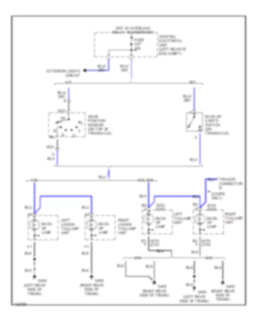
Back-up Lamps Wiring Diagram for Volvo V70 T-5 1999
List of elements for Back-up Lamps Wiring Diagram for Volvo V70 T-5 1999:
- (coupe only)
- (left rear side of trunk)
- (right rear side of trunk)
- (s70) (c70)
- (s70) b3 (c70)
- 15i
- A/t
- Back- up lamp
- Back-up lights switch (on transaxle)
- C70
- C70, s70
- Central electrical unit (left rear of eng compt)
- Connector b
- Exterior lights circuit
- Fuse c27 15a
- G404
- G405
- Gear position sensor (on top of transaxle)
- Hot w/ overload relay 15i energized
- Left lower taillamp unit
- Left taillamp unit
- M/t
- Nca
- Right lower taillamp unit
- Right taillamp unit
- S70
- V70
Exterior Lamps Wiring Diagram (1 of 2) for Volvo V70 T-5 1999
List of elements for Exterior Lamps Wiring Diagram (1 of 2) for Volvo V70 T-5 1999:
- 15i
- 15i-rail connector
- 54h
- 54l
- 54r
- 56b
- 58a
- 58b
- 58c
- 58la
- 58lb
- 58ra
- 58rb
- Central electrical unit (left rear of eng compt)
- Fuse c11 10a
- Fuse c23 10a
- Fuse c24 10a
- Fuse c26 15a
- Fuse c29 10a
- Fuse c8 15a
- G102 (left front strut tower)
- G404 (left rear side of trunk)
- Head
- Headlights system
- High- mount stop lamp
- Hot at all times
- Hot w/ overload relay 15i energized
- Interior lights (rheostat)
- Left front park/turn lamp
- Left tunr signal flsher
- License plate light
- Light switch
- Main headlight relay/bulb failure warning sensor
- Model only
- Off
- Park
- Power ground connector (in central electrical unit)
- Rear bulb failure warning sensor (left side of luggage compt)
- Red
- Right front park/ turn lamp
- Right tunr signal flsher
- Shift interlock system
- Stoplight switch (on brake pedal support)
Exterior Lamps Wiring Diagram (2 of 2) for Volvo V70 T-5 1999
List of elements for Exterior Lamps Wiring Diagram (2 of 2) for Volvo V70 T-5 1999:
- ('99) ('00)
- (in central electrical unit)
- 15a
- 15i
- 49a
- A12
- A13
- A17
- A18
- Acc
- B10
- Back- up lamp
- Back-up lamps circuit
- Bulb malfunction indicator
- Central electrical unit (left rear of eng compt)
- Central locking/ anti-theft alarm control module (behind lower left end of dash)
- Fuse c13 15a 20a
- Fuse c27 15a
- G102 (left front strut tower)
- G404 (left rear side of trunk)
- G405 (right rear side of trunk)
- Hazard flasher relay/ switch
- Headlights system
- Hot at all times
- Hot w/ overload relay 15i energized
- Ignition switch
- Illum- ination lamp
- Instrument cluster
- Interior lights system
- Left lower tail lamp unit
- Left turn indicator
- Left upper tail lamp unit
- Model only
- Off
- Park lamp
- Pnk
- Power ground connector
- Rear fog/ park lamp
- Red
- Right lower tail lamp unit
- Right turn indicator
- Right upper tail lamp unit
- Solid state
- Start
- Stop lamp
- Trailer indicator
- Turn signal lamp
- Turn signal/ high-low beam switch
GROUND DISTRIBUTION
Ground Distribution Wiring Diagram for Volvo V70 T-5 1999
List of elements for Ground Distribution Wiring Diagram for Volvo V70 T-5 1999:
- (s70)
- (v70)
- 31/11
- 31/12
- 31/15
- 31/32
- 31/33
- 31/4
- 31/44
- 31/47
- 31/48
- 31/50
- 31/51
- 31/52
- 31/55
- 31/65
- 31/7
- A/c control panel
- Abs control module
- Accelerator pedal position sensor
- Air distribution valve
- Air preheating ptc resistor
- Alarm horn
- Alarm siren
- Alarm siren (convertible)
- Alarm/electronic immobilizer indicator
- Amplifier
- Antenna amplifier
- Aw 50-42 mode selector
- Aw 50-42 transmission control module
- Battery
- Blower fan
- Blower fan power module
- Brake fluid level sensor
- Cabin temper- ature sensor
- Car tilt sensor
- Cargo compart- ment fans switch
- Cd-changer
- Central electrical unit (left rear of eng compt)
- Central locking/ alarm remote control unit
- Central locking/ anti-theft alarm control module
- Cruise control module
- Data link connector
- Driver's side rearview mirror switch
- Electronic climate control module
- Electronic start inhibitor
- Engine control module
- Engine coolant fan
- Engine coolant level switch
- Front ashtray illumination lamp
- Front cigarette lighter
- Front fog- light switch
- Front washer motor
- Fuel pump
- Fuel pump relay
- Fuel tank filler flap central locking motor
- G101 (left front fender panel, behind battery)
- G102 (left front shock tower)
- G102 (left front strut tower)
- G107 (below right headlamp)
- G110 (left side of engine)
- G112 (left side of engine)
- G125 (front of engine)
- G134 (top of engine)
- G303 (on right rear crossmember)
- G304 (on left rear crossmember)
- G404 (left rear side of trunk)
- G405 (right rear side of trunk)
- G900 (left "a" pillar)
- G901 (right "a" pillar)
- G904 (left "c" pillar)
- Garage door opener remote control module
- Gear selector illumination lamp
- Glass breakage sensor
- Glove box 1/1- lamp
- Group 1 spark plugs
- Group 2 spark plugs
- Hazard flasher/ relay switch
- Heated rear seat switch
- Heated seat relay (rear)
- High mounted stoplights (coupe)
- Highmount stop lamp
- Highmount stop lamp (convertible)
- Hood alarm switch
- Ignition discharge module & ignition coil
- Instrument cluster
- Interior lighting switch (convertible)
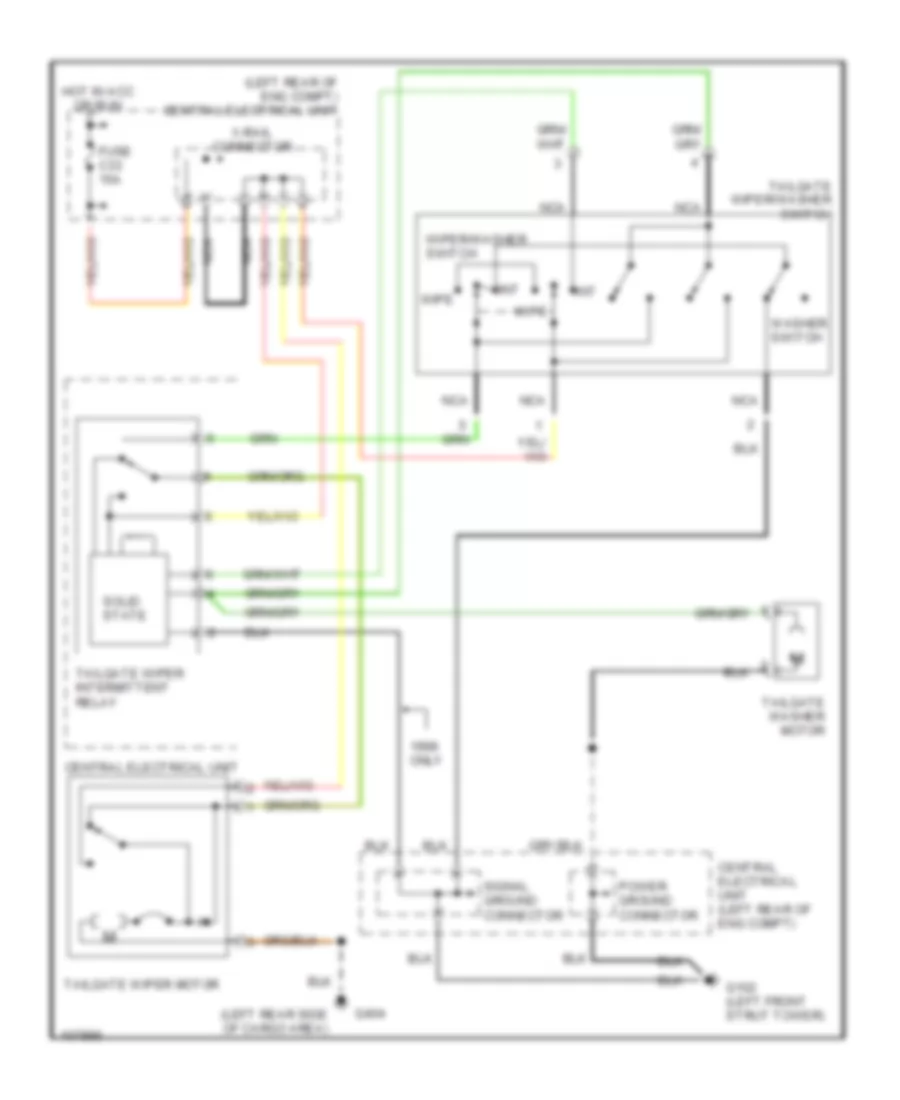
- Intermittent tailgate wiper relay (v70)
- Kickdown switch throttle mechanism
- Left cargo compartment fan
- Left front door lock
- Left front foglight
- Left front heated seat switch
- Left front park/turn signal lamps
- Left front power window switch
- Left front seat control module
- Left headlamp
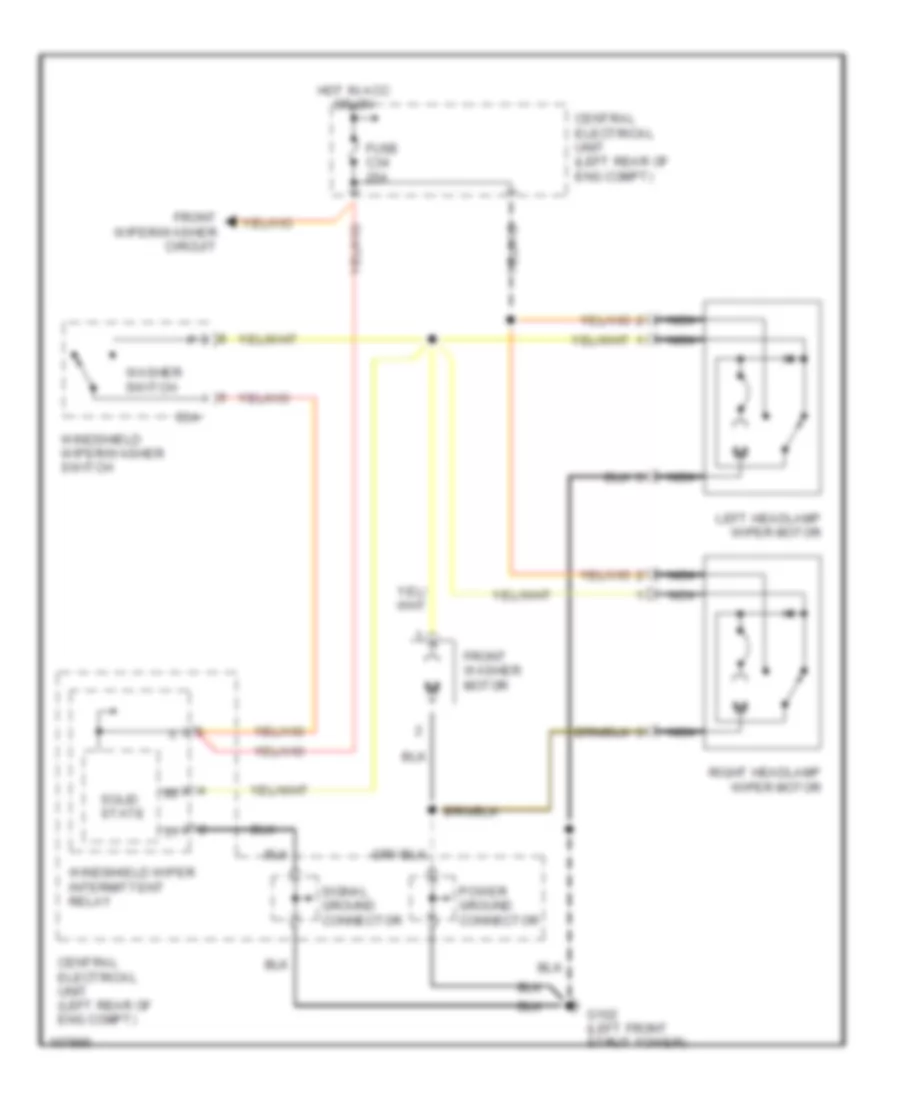
- Left headlamp washer motor
- Left license plate lamp
- Left movement detector (s70, v70)
- Left rear backrest bass speaker filter (convertible)
- Left rear lock unit
- Left rear power window switch (convertible)
- Left rear reading lamp
- Left rear reading lamp (convertible)
- Left rear seat heater pad
- Left side vanity mirror lamp
- Left side vanity mirror lamp (convertible)
- Left tail lamp
- Left turn signal flasher
- License plate lamps
- Light switch
- Main headlight relay (w/ bulb failure warning sensor)
- Movement detector (c70)
- Overhead console
- Passenger side air bag disconnection contact breaker
- Passenger side rear view mirror switch
- Power antenna
- Power door mirrors switch
- Power door mirrors switch (convertible)
- Power ground connector
- Power sun roof control module
- Power sun roof switch
- Power windows control module
- Radio
- Rear bulb failure warning sensor
- Rear cigarette lighter
- Rear fog- light switch
- Rear view mirror
- Rear view mirror (c70)
- Rear view mirror switches (convertible)
- Rear window heated element
- Rear window heating element (convertible)
- Rear window/ door mirror heated switch
- Retracting door mirrors switch
- Rheostat
- Right cargo compartment fan
- Right front door lock
- Right front fog lamp
- Right front heated seat switch
- Right front park lamp/ turn signal lamp
- Right front power window switch
- Right front seat control module
- Right headlamp
- Right headlamp washer motor
- Right license plate lamp
- Right movement detector (s70, v70)
- Right rear backrest bass speaker filter (convertible)
- Right rear door lock unit (s70, v70)
- Right rear power window switch (convertible)
- Right rear reading lamp
- Right rear reading lamp (convertible)
- Right rear seat heater pad
- Right side turn signal lamp
- Right side vanity mirror lamp
- Right tail lamp
- Rti cd-player
- Rti control module
- Rti display
- Seat belt reminder/key warning relay
- Shift lock solenoid
- Signal ground connector
- Soft-top acknowledgment signal speaker (convertible)
- Soft-top control module
- Soft-top switch (convertible)
- Tailgate lock unit
- Tailgate washer motor
- Tailgate wipe/washer switch (v70)
- Tailgate wiper motor
- Throttle body control module
- Tracs switch
- Trunk lid/ fuel tank cover switch
- Tv receiver
- Washer fluid level sensor
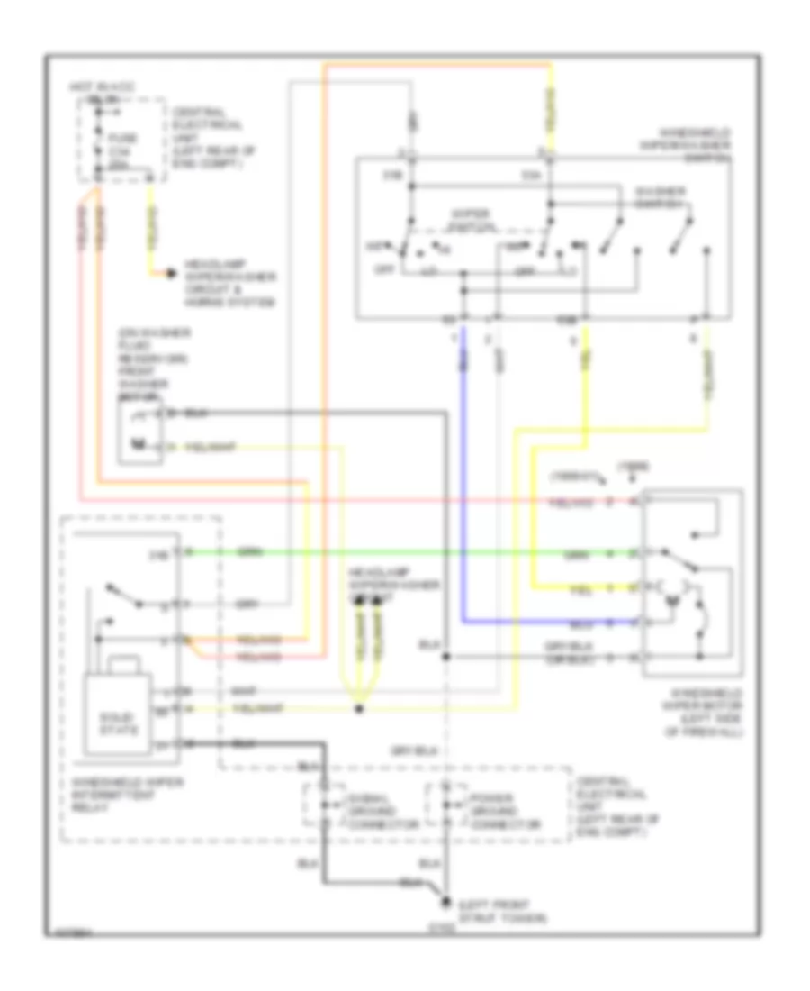
- Windshield intermittent wiper relay
- Windshield wiper motor
HEADLIGHTS
Headlight Wiring Diagram (1 of 2) for Volvo V70 T-5 1999
List of elements for Headlight Wiring Diagram (1 of 2) for Volvo V70 T-5 1999:
- (others) ('00 s70 & s70)
- 15i
- 2000-01 model only
- 56a
- 56b
- 56b6l
- 56b6r
- 56bs
- 81a
- Bulb failure warning sensor (rear) (left side of luggage compt)
- Canada only
- Central electrical unit (left rear of eng compt)
- Engine compt relay/ fuse box (left side of eng compt, next to strut tower)
- Flash
- Fuse a5 50a
- Fuse c13 15a 20a
- Fuse c18 10a
- Fuse c19 15a
- Fuse c20 15a
- Fuse c21 15a
- Fuse c22 15a
- Fuse c26 15a
- Fuse c8 15a
- G102 (left front strut tower)
- Head
- High
- Hot at all times
- Hot w/ key in ignition
- Hot w/ overload relay 15i energized
- Illumination lamps
- Interior lights
- Left headlight
- Light switch
- Main headlight relay/ bulb failure warning sensor
- Off
- Park
- Pnk
- Red
- Right headlight
- Signal ground connector
- Solid state
- System (rheostat)
- Turn signal/ high-low beam switch
- Usa & canada
Headlight Wiring Diagram (2 of 2) for Volvo V70 T-5 1999
List of elements for Headlight Wiring Diagram (2 of 2) for Volvo V70 T-5 1999:
- (1999 c70)
- (1999 c70) (others)
- (conv)
- (others)
- (right rear side of trunk)
- 15a
- 2000-01
- A17
- A18
- Acc
- B10
- Bulb failure warning indicator
- C70
- Central electrical unit (left rear of eng compt)
- Exterior lights system
- Foglight relay
- Front foglight switch
- Front foglights bridge
- Fuse
- Fuse c17 20a
- Fuse c2 10a 15a
- G102 (left front strut tower)
- G404 (left rear side of trunk)
- G405
- G405 (right rear side of trunk)
- High beam indicator
- Hot at all times
- Ignition switch
- Illumination lamp
- Instrument cluster
- Interior lights system (rheostat)
- Left front foglight
- Left lower tail- light unit
- Left tail- light unit
- Left taillight unit
- Lock
- Off
- On indicator
- Pnk
- Power ground connector
- Rear fog- light
- Rear fog- lights indicator
- Rear fog/park lamp
- Rear foglight switch
- Red
- Right front foglight
- Right lower tail- light unit
- Right tail- light unit
- Right taillight unit
- S70
- Start
- V70
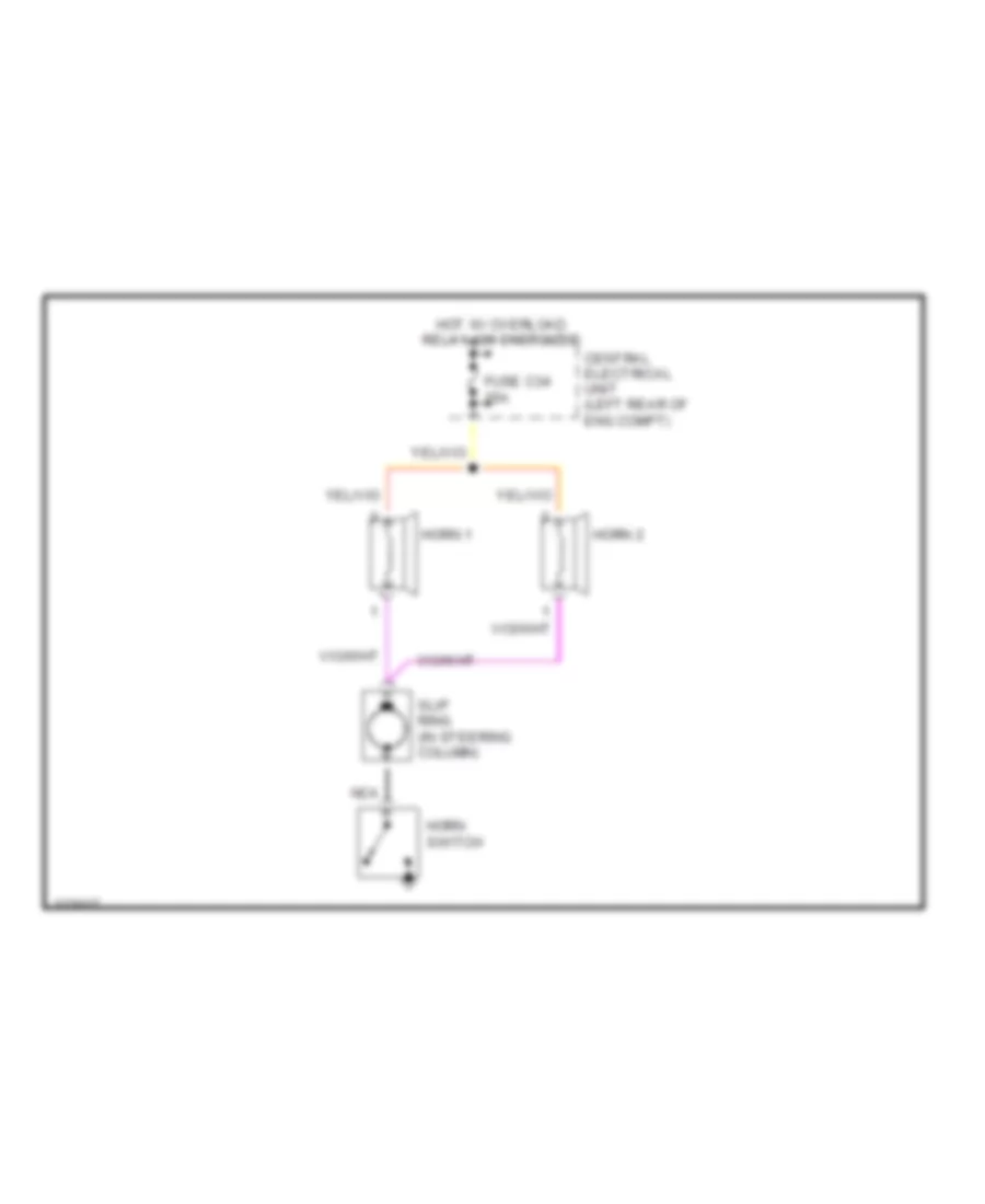
HORN
Horn Wiring Diagram for Volvo V70 T-5 1999
List of elements for Horn Wiring Diagram for Volvo V70 T-5 1999:
- Central electrical unit (left rear of eng compt)
- Fuse c34 25a
- Horn 1
- Horn 2
- Horn switch
- Hot w/ overload relay 105 energized
- Nca
- Slip ring (in steering column)
INSTRUMENT CLUSTER
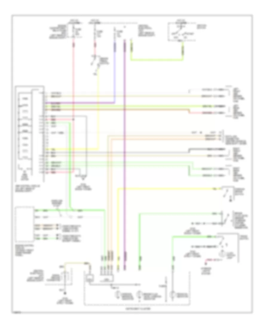
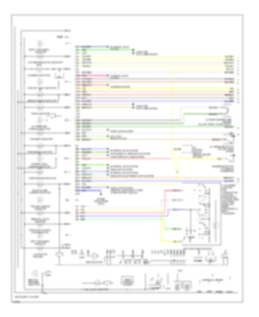
Instrument Cluster Wiring Diagram (1 of 2) for Volvo V70 T-5 1999
List of elements for Instrument Cluster Wiring Diagram (1 of 2) for Volvo V70 T-5 1999:
- consumption
- empty
- fuel consumption 3 avg fuel
- since last reset
- 1 avg speed 2 instant
- 4 outside temp 5 distance
- 5v reg.
- 6 distance to
- 7 diagnosis
- 8v reg.
- A10
- A11
- A12
- A13
- A14
- A15
- A16
- A17
- A18
- A19
- A20
- A21
- A22
- A23
- A24
- A25
- A26
- A27
- A28
- A29
- A30
- Anti-lock brake system
- B10
- B11
- B12
- B13
- B14
- B15
- B16
- Brake warning indicator
- Bulb failure warning indicator
- Charging indicator
- Charging system
- Check engine indicator
- Clock "h"
- Clock "m"
- Computer data lines system
- Coolant level indicator
- Cpu
- Cross coil driver
- Door locks system
- Door locks system (central locking/anti-theft alarm control module)
- Exterior lights system
- Filter
- Fuel
- Fuel level indicator
- Fuse
- Handbrake switch (at base of handbrake)
- Headlights & exterior lights system
- Headlights system
- High beam indicator
- I/f
- Illumination (5 bulbs)
- Indicator
- Instrument cluster
- Interior lights system
- Lcd cdo/ trip
- Lcd trip/ com
- Left turn signal indicator
- Low gear selection indicator
- Nvm
- Oil pressure
- Oil pressure switch (on left rear of eng)
- Outside temperature sensor (on left front of eng compt)
- Park brake indicator
- Pnk
- Power tops system (conv)
- Rear fog lights indicator
- Reset
- Right turn signal
- Rti control module (behind center of dash)
- Service reminder indicator
- Speed
- Speed warning buzzer
- Srs indicator
- Tacho
- Temp
- Tracs indicator
- Trailer warning indicator
- Trip computer controls
- Trip reset
- Trunk or tailgate ajar indicator
- Warning indicator
- Washer level
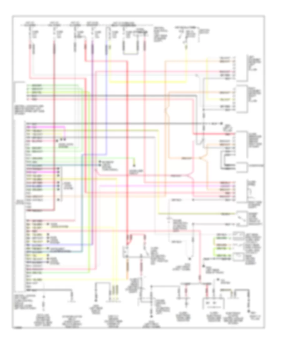
Instrument Cluster Wiring Diagram (2 of 2) for Volvo V70 T-5 1999
List of elements for Instrument Cluster Wiring Diagram (2 of 2) for Volvo V70 T-5 1999:
- 15a
- 2wd
- 4wd
- Acc
- Aw 50-42 automatic transmission control module (on right front inner fender panel, in control module box)
- Aw 50-42 mode selector
- B21
- B27
- B39
- Brake fluid level switch (on brake fluid reservoir)
- Central electrical unit (left rear of eng compt)
- Central locking/anti-theft alarm control module (behind lower left end of dash)
- Data
- Electronic climate control module (center of dash)
- Engine control module (on right front inner fender panel, in control module box)
- Engine coolant level switch (right front of engine compt)
- Fuel level sensor (in fuel tank)
- Fuse c8 15a
- G102 (left front strut tower)
- Hot at all times
- Ignition switch
- Left fuel level sensor (in fuel tank)
- Light switch
- Low gear
- Mil
- Off
- Power ground connector
- Radio
- Right fuel level sensor (in fuel tank)
- Rpm out
- Rti control module (behind center of dash)
- Signal ground connector
- Speed input
- Start
- Temp input
- Temp out
- Washer fluid level switch (in washer fluid reservoir)
INTERIOR LIGHTS
Courtesy Lamps Wiring Diagram for Volvo V70 T-5 1999
List of elements for Courtesy Lamps Wiring Diagram for Volvo V70 T-5 1999:
- (2 bulbs)
- (left "a'" pillar)
- (left front strut tower)
- (left rear side of trunk) g404
- 1999-2000 s70
- 1999-2001 v70
- A19
- A23
- A24
- A26
- Central electrical unit (left rear of eng compt)
- Central locking/ anti-theft alarm control module (behind lower left end of dash)
- Door
- Fuse c13 15a
- Fuse c15 10a
- Fuse c3 10a
- Fuse c35 10a
- Fuse c6 20a
- G102
- G303 (on right rear crossmember)
- G404 (left rear side of trunk)
- G900
- G900 (left "a" pillar)
- G901 (right "a" pillar)
- Glove box lamp
- Hot at all times
- Hot in acc or on
- Hot in on or start
- Ignition lighting/ antenna ring (left side of steering column)
- Left front door lock
- Left front footwell lamp
- Left front open-door warning lamp
- Left rear lock unit
- Left rear open-door warning lamp
- Left rear reading lamp
- Left vanity mirror lamp
- Nca
- Overhead console
- Power ground connector
- Red
- Right front door lock
- Right front footwell lamp
- Right front open-door warning lamp
- Right rear lock unit
- Right rear open-door warning lamp
- Right rear reading lamp
- Right vanity mirror lamp
- Seatbelt indicator
- Solid state
- Trunk lamp
- Trunk/tailgate switch
- Warning system
Instrument Illumination Wiring Diagram for Volvo V70 T-5 1999
List of elements for Instrument Illumination Wiring Diagram for Volvo V70 T-5 1999:
- (5 bulbs)
- (not used)
- 15i
- 56b
- A/c control panel
- A/t mode selector
- A10
- A14
- A16
- A17
- A23
- B16
- B18
- Central electrical unit
- Central electrical unit (left rear of eng compt)
- Convertible
- Electronic climate control module
- Except convertible
- Front ashtray illumination lamp
- Front foglight switch
- Fuse c26 15a
- Fuse c35 10a
- Fuse c8 15a
- G102 (left front strut tower)
- G900 (left "a' pillar)
- G901 (right "a' pillar)
- Gear selector illumination lamp
- Hazard flasher relay/switch
- Head
- Headlights system
- Heated rear window/door mirrors switch
- Hot at all times
- Hot in acc or on
- Hot w/ overload relay 105 energized
- Instrument cluster
- Left front heated seat switch
- Light switch
- Off
- Park
- Pnk
- Power ground connector
- Power sun roof switch
- Radio
- Rear foglight switch
- Rheostat
- Right front heated seat switch
- Rti control module
- Rti display
- Soft-top switch
- Tracs switch
- W/ auto a/c
- W/ manual a/c
MEMORY SYSTEMS
Driver's Memory Seat Wiring Diagram for Volvo V70 T-5 1999
List of elements for Driver's Memory Seat Wiring Diagram for Volvo V70 T-5 1999:
- A10
- A11
- A12
- A13
- A14
- A15
- A16
- Back
- Backrest switch
- C10
- C11
- C12
- C13
- C14
- Central electrical unit (left rear of engine compt)
- Circuit breaker
- Data link connector (dlc) (on center console, near shift lever)
- Down
- Forw
- Forw-backw switch
- Front edge switch
- G901 (right "a" pillar)
- Hot at all times
- Left front seat backrest motor
- Left front seat control module (under driver's seat)
- Left front seat control unit
- Left front seat forward-backward motor
- Left front seat front edge up-down motor
- Left front seat rear edge up-down motor
- Left lower backrest contact breaker (c70 only)
- Left upper backrest contact breaker (c70 only)
- M1+
- M1-
- M2+
- M2-
- M3+
- M3-
- M4+
- M4-
- Mem
- Nca
- R1+
- R1-
- R2+
- R2-
- R3+
- R3-
- R31
- R4+
- R4-
- Rear edge switch
- Red
- Vangle
- Vfold
- Vg1
- Vg2
- Vg3/4
- Vga
- Vgf
- Vr1
- Vr2
- Vr3
- Vr4
NAVIGATION
Navigation Wiring Diagram for Volvo V70 T-5 1999
List of elements for Navigation Wiring Diagram for Volvo V70 T-5 1999:
- (other) ('00 conv)
- A/t
- Back-up lights switch (on transaxle)
- Brake ind
- Central electrical unit (left rear of eng compt)
- Computer data lines system
- Fuse c15 10a
- Fuse c27 15a
- Fuse c3 10a 15a
- Fuse c35 10a
- G900 (left "a" pillar)
- Gear position sensor (on top of transaxle)
- Hot at all times
- Hot in start or on
- Instrument cluster
- M/t
- Nca
- Parking brake switch
- Pnk
- Radio
- Radio system
- Red
- Rheostat
- Rti cd player
- Rti control module (behind center of dash)
- Rti display
- Rti tmc/fm receiver (behind right side of dash)
- Speed
- Tv tuner
POWER DISTRIBUTION
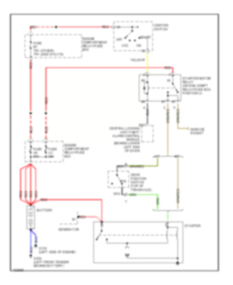
Accessories Connector Wiring Diagram for Volvo V70 T-5 1999
List of elements for Accessories Connector Wiring Diagram for Volvo V70 T-5 1999:
- Accessory connector (left side of dash)
- Central electrical unit (left rear of eng compt)
- Fuse c16 30a
- Fuse c19 15a
- Fuse c35 10a
- G102 (left front strut tower)
- Hot at all times
- Pnk
- Power ground connector
- Red
- Rheostat
- Turn signal/ high-low beam switch
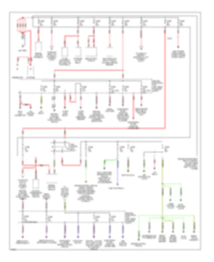
Power Distribution Wiring Diagram (1 of 3) for Volvo V70 T-5 1999
List of elements for Power Distribution Wiring Diagram (1 of 3) for Volvo V70 T-5 1999:
- (c70)
- A/c control panel
- A/c relay
- A10
- Abs control module
- Air distribution valve
- Air preheating ptc resistor
- Alarm horn relay
- Alarm siren, glass breakage sensor
- Aw 50-42 transmission control module
- Aw 50-42 transmission control module, a/c relay
- B11
- B38
- Battery
- Central electrical unit (left rear of engine compt)
- Central locking/ alarm remote control module, movement detectors
- Central locking/ anti-theft alarm control module
- Central locking/ anti-theft alarm control module, rti control module
- Conv.
- Data link connector
- Electronic start inhibitor (immobilizer)
- Electronic start inhibitor (immobilizer), light switch, instrument cluster
- Engine compartment relay/fuse box (on left rear of eng compt. next to strut tower)
- Engine control module
- Engine control module, throttle body control module, accelerator pedal position sensor,
- Engine cooling fan relay
- Evap canister valve
- Evap valve
- Front heated oxygen sensor
- Fuel injectors, engine control module mass airflow sensor/air volume sensor
- Fuel pump relay
- Fuel system main relay
- Fuse a1 60a
- Fuse a2 50a
- Fuse a3 50a
- Fuse a4 50a
- Fuse a5 50a
- Fuse a6 60a
- Fuse a7 50a
- Fuse a8 60a
- Fuse a9 60a
- Fuse b1 15a
- Fuse b2 15a
- Fuse b3 15a
- Fuse b4 15a
- Fuse b5 20a
- Fuse c1 10a (convertible)
- Fuse c10 10a
- Fuse c2 10a
- Fuse c3 10a
- Fuse c4 10a
- Fuse c5 15a
- Fuse c6 20a
- Fuse c7 15a 20a
- Fuse c8 15a
- Fuse c9 30a 20a
- Generator
- Ignition coils
- Instrument cluster, engine control module
- Left power window relay & right power window relay
- Main headlight relay (w/bulb failure warning sensor)
- Pulse secondary air injection pump relay
- Radio, amplifier
- Rear foglight switch
- Rear foglights, instrument cluster
- Rear hatch opening relay
- Rear heated oxygen sensor
- Rear heated seat relay, amplifier (c70)
- Red
- Reset valve camshaft
- Starter
- Starter motor relay
- Stoplight switch
- To fuse c13 central electrical unit (diagram 2 of 3)
- To ignition switch (pin 15a) (diagram 3 of 3)
- To ignition switch (pin 30) (diagram 3 of 3)
- Turbo control valve
Power Distribution Wiring Diagram (2 of 3) for Volvo V70 T-5 1999
List of elements for Power Distribution Wiring Diagram (2 of 3) for Volvo V70 T-5 1999:
- (coupe)
- (not used)
- Accessory connector
- Amplifier (c70), additional heater
- Cargo area lighting, right front door open warning lamp, left front door open warning lamp, right vanity mirror lamp, passenger compartment roof lamp, interior lighting switch, left rear door open warning lamp, right rear door open warning lamp, power windows control module
- Central electrical unit (left rear of engine compt)
- Central locking/ anti-theft alarm control module
- Circuit breaker
- Circuit breaker (conv)
- Circuit breaker (ex. conv.)
- Circuit breaker (conv.)
- Convertible
- Foglight relay
- From fuse a7 (diagram 1 of 3)
- Fuse c11 10a
- Fuse c12 30a
- Fuse c13 15a
- Fuse c14 30a 40a
- Fuse c15 10a
- Fuse c16 30a
- Fuse c17 20a
- Fuse c18 10a
- Fuse c19 15a
- Fuse c20 15a
- Fuse c21 15a
- Fuse c22 15a
- Fuse c23 10a
- Fuse c24 10a
- Fuse c25 10a
- Glove box lamp, left front footwell lamp, & right front footwell lamp
- Heated rear window/door mirrors relay
- Ignition lighting/ antenna ring
- Instrument cluster (hi beam)
- Left front park/turn lamp
- Left front power window relay
- Left headlight
- Left seat control module, left seat control unit
- Light switch
- Main head- lamp relay (w/ bulb failure warning sensor), seat belt reminder/ key warning relay
- Main headlight relay (w/ bulb failure warning sensor)
- Nca
- Power sun roof control module, power window switches
- Power window control module
- Power window control module, front door power window switches, power door mirrors
- Rear bulb failure warning sensor, license plate lamps, trailer connector a
- Rear bulb failure warning sensor, trailer connector a
- Red
- Right front park/turn lamp
- Right front power window relay
- Right headlight
- Right seat control module, right seat control unit
- Rti display, rti control module, rti cd-player
- Soft-top control module
- Stoplight switch
- To ignition switch (pin s) (diagram 3 of 3)
- Turn signal/ high-low beam switch
- Turn signal/high low beam switch, hazard flasher relay/switch
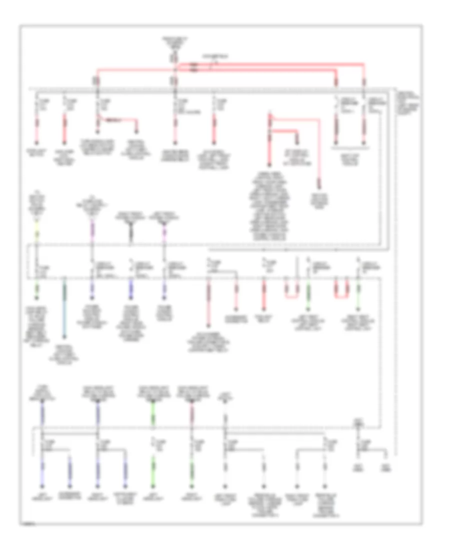
Power Distribution Wiring Diagram (3 of 3) for Volvo V70 T-5 1999
List of elements for Power Distribution Wiring Diagram (3 of 3) for Volvo V70 T-5 1999:
- (c70) (s70, v70)
- 15a
- 15i-rail connector
- A/c control panel, blower fan, blower fan power unit
- Acc
- Additional heater
- Alarm siren
- Back-up lamps switch
- Central electrical unit (left rear of eng compt)
- Central electrical unit (left rear of engine compt)
- From circuit breaker c37 (diagram 2 of 3)
- From fuse a2 (diagram i of 3)
- From fuse b1 (diagram 1 of 3)
- From fuse c18 (diagram 2 of 3)
- From fuse c3 & c4 (diagram 1 of 3)
- Front cigar lighter
- Fuse c26 15a
- Fuse c27 15a
- Fuse c28 25a
- Fuse c29 10a
- Fuse c30 15a 20a
- Fuse c31 25a
- Fuse c32 10a
- Fuse c33 15a
- Fuse c34 25a
- Fuse c35 10a
- Fuse c36 15a
- G102 (left front strut tower)
- G901 (right "a" pillar)
- Gear position sensor
- Hazard flasher relay/ switch
- Heated front seat switches, heated rear seat relay, heated rear seat switch
- Heated rear window/door mirrors relay
- Horn 1, horn 2, headlamp wiper motors
- Ignition switch
- Instrument cluster
- Intermittent wiper relay (tailgate)
- Key in ignition switch
- Key-in
- Left vanity mirror light, rear view mirror, passenger compartment roof lamp, rti control module, rti cd-player, rti display, left seat control unit
- Light switch
- Off
- Overload relay 15i
- Power ground connector
- Radio, rear bass speaker switch, trunk lid opening relay, power sun roof switch, folding door mirror switch, ecc climate control module
- Rear bulb failure warning sensor, trailer connector b
- Rear cigar lighter
- Rear view mirror, accessory connector, soft top audible signal, power window switches, cargo compartment fans switch
- Red
- Roll bar control module
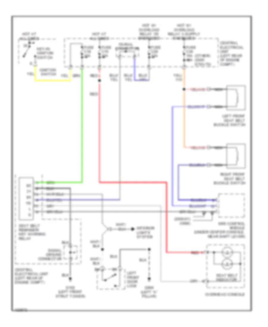
- Seat belt buckle switches
- Seat belt reminder/ key warning relay
- Soft-top control module, rheostat
- Srs crash sensor
- Start
- Starter motor relay
- Tailgate wiper motor
- Tailgate wiper/ washer switch
- Windshield wiper intermittent relay, front washer motor
- Windshield wiper motor
- X-rail connector
POWER DOOR LOCKS
Power Door Lock Wiring Diagram for Volvo V70 T-5 1999
List of elements for Power Door Lock Wiring Diagram for Volvo V70 T-5 1999:
- ('99) ('00)
- (left rear side of trunk)
- (w/o deadlock) (w/ deadlock)
- 15a
- A10
- A11
- A12
- A13
- A14
- A15
- A16
- A17
- A18
- A19
- A20
- A21
- A22
- A23
- A24
- A25
- A26
- Acc
- B10
- B11
- B12
- B13
- B14
- B15
- B16
- B17
- B18
- B19
- Boot lid
- Central electrical unit
- Central locking motor (near fuel tank cover)
- Central locking/ anti-theft alarm control module (behind lower left end of dash)
- Central locking/alarm remote control unit (behind upper left side of dash)
- Data link connector (on center console, near shift lever)
- Exterior lights system (turn signal)
- Fuel
- Fuse
- Fuse c10 10a
- Fuse c13 15a 20a
- Fuse c3 10a
- Fuse c6 20a
- G304 (left rear crossmember)
- G404
- G405 (right rear side of trunk)
- G900 (left "a" pillar)
- Hot at all times
- Ignition switch
- Instrument cluster
- Instrument cluster system
- Key in ignition switch
- Left front door lock
- Left front power window switch
- Left rear door lock
- Lock
- Off
- Red
- Right front door lock
- Right front power window switch
- Right rear door lock
- Right taillamp unit
- Solid state
- Start
- Tailgate indicator
- Tailgate locking unit (rear center of trunk)
- Trunk lid/fuel tank cover switch
- Unlock
POWER MIRRORS
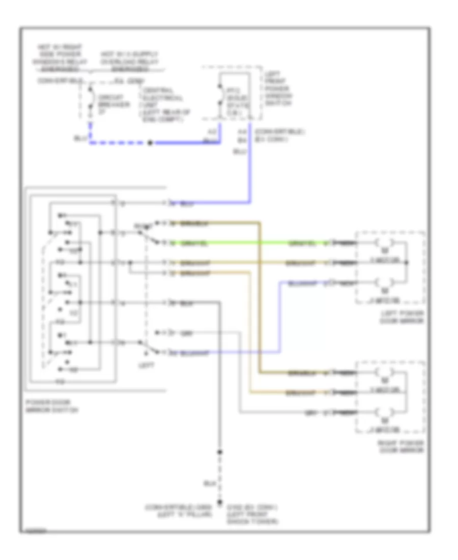
Fold-back Mirrors Wiring Diagram for Volvo V70 T-5 1999
List of elements for Fold-back Mirrors Wiring Diagram for Volvo V70 T-5 1999:
- (left front strut tower)
- (not used)
- (right "a" pillar)
- 15i
- 15i rail connector
- 87b
- Central electrical unit
- Circuit breaker
- Driver's door power window switch
- Driver's side power door mirror
- Folding door mirrors switch
- Front passenger door power window switch
- Fuse c14 40a (coupe) 30a (ex coupe)
- Fuse c29 10a
- Fuse c32 10a
- G102
- G102 (left front strut tower)
- G901
- Heated rear window/door mirror relay (on central electrical unit)
- Heated rear window/door mirrors switch
- Hot at all times
- Interior lights system
- Passenger's side power door mirror
- Pnk
- Red
Power Mirrors Wiring Diagram for Volvo V70 T-5 1999
List of elements for Power Mirrors Wiring Diagram for Volvo V70 T-5 1999:
- (convertible) (ex conv)
- (convertible) g900 (left "a" pillar)
- Central electrical unit (left rear of eng compt)
- Circuit breaker
- Convertible
- Ex conv
- G102 (ex conv) (left front shock tower)
- Hot w/ right side power windows relay energized
- Left
- Left front power window switch
- Left power door mirror
- Nca
- Power door mirror switch
- Ptc (solid state c.b.)
- Right
- Right power door mirror
- X-motor
- Y-motor
POWER SEATS
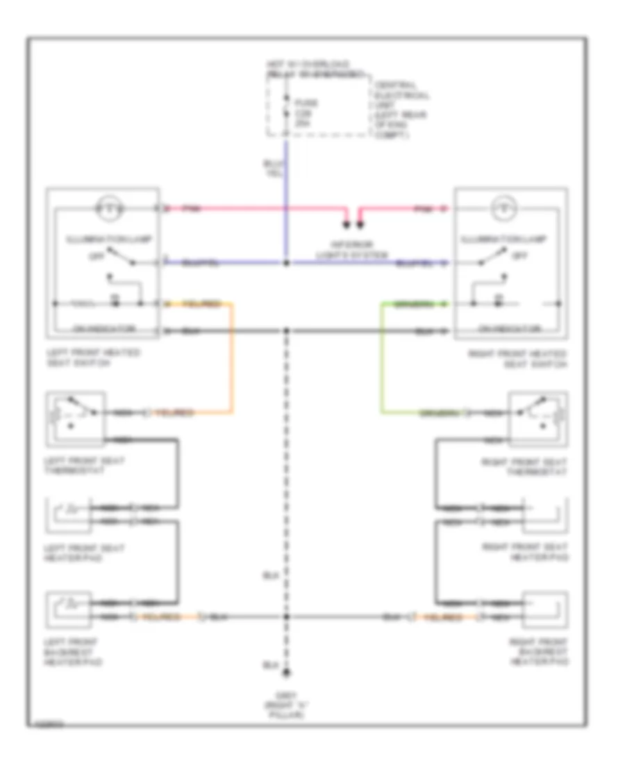
Front Seat Heater Wiring Diagram for Volvo V70 T-5 1999
List of elements for Front Seat Heater Wiring Diagram for Volvo V70 T-5 1999:
- Central electrical unit (left rear of eng compt)
- Fuse c28 25a
- G901 (right "a" pillar)
- Hot w/ overload relay 15i energized
- Illumination lamp
- Interior lights system
- Left front backrest heater pad
- Left front heated seat switch
- Left front seat thermostat
- Left front seat heater pad
- Nca
- Off
- On indicator
- Pnk
- Right front backrest heater pad
- Right front heated seat switch
- Right front seat heater pad
- Right front seat thermostat
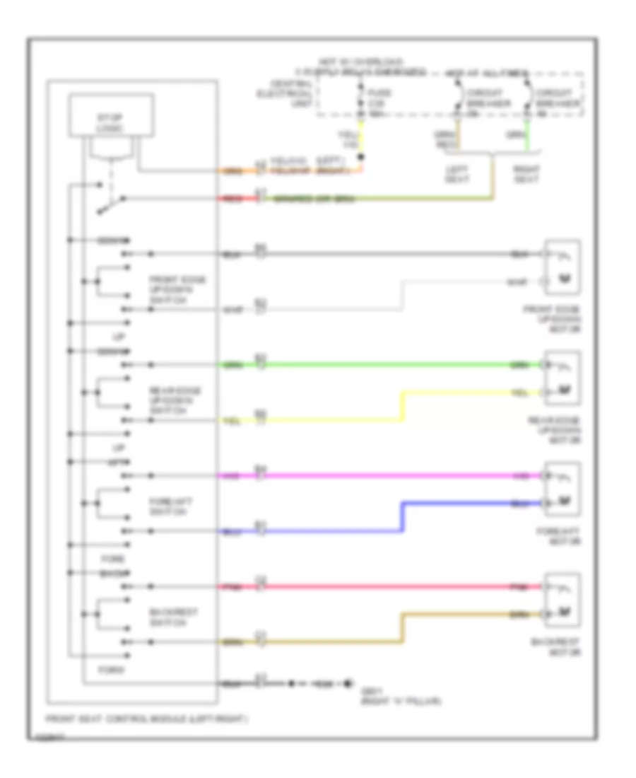
Power Seats Wiring Diagram for Volvo V70 T-5 1999
List of elements for Power Seats Wiring Diagram for Volvo V70 T-5 1999:
- (left) (right)
- Aft
- Back
- Backrest motor
- Backrest switch
- Central electrical unit
- Circuit breaker
- Down
- Fore
- Fore/aft motor
- Fore/aft switch
- Forw
- Front edge up/down motor
- Front edge up/down switch
- Front seat control module (left/right)
- Fuse c35 10a
- G901 (right "a" pillar)
- Hot at all times
- Left seat
- Pnk
- Rear edge up/down motor
- Rear edge up/down switch
- Red
- Right seat
- Stop logic
Rear Heated Seats Wiring Diagram for Volvo V70 T-5 1999
List of elements for Rear Heated Seats Wiring Diagram for Volvo V70 T-5 1999:
- Central electrical unit (left rear of eng compt)
- Fuse c28 25a
- Fuse c9 20a
- G303 (on right rear crossmember)
- G901 (right "a" pillar)
- Heated seat relay (rear) (under center floor console)
- Hot at all times
- Hot w/ overload relay 106 energized
- Illumination lamp
- Left rear seat backrest heater pad
- Left rear seat heater pad
- Left rear seat thermostat
- Nca
- Off
- On indicator
- Rear heated seat switch
- Red
- Right rear seat backrest heater pad
- Right rear seat heater pad
- Right rear seat thermostat
POWER TOP/SUNROOF
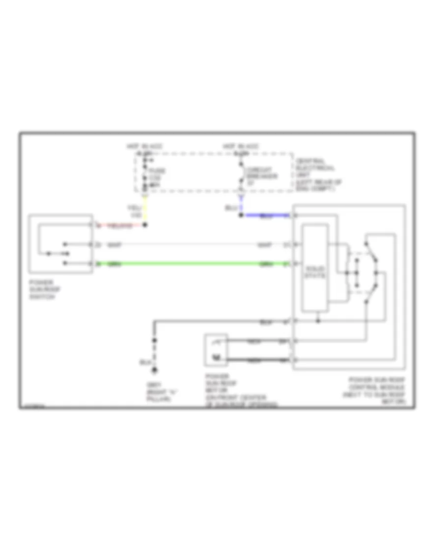
Sunroof Wiring Diagram for Volvo V70 T-5 1999
List of elements for Sunroof Wiring Diagram for Volvo V70 T-5 1999:
- Central electrical unit (left rear of eng compt)
- Circuit breaker
- Fuse c32 10a
- G901 (right "a" pillar)
- Hot in acc & on
- Nca
- Power sun roof control module (next to sun roof motor)
- Power sun roof motor (on front center of sun roof opening)
- Power sun roof switch
- Solid state
POWER WINDOWS
Power Window Wiring Diagram for Volvo V70 T-5 1999
List of elements for Power Window Wiring Diagram for Volvo V70 T-5 1999:
- Central electrical unit
- Circuit breaker c37
- Driver
- G102 (left front strut tower)
- Left front power window switch
- Left front window motor
- Left rear
- Left rear power window switch
- Left rear window motor
- Nca
- Power door mirror switch
- Power ground connector
- Ptc (solid state circuit breaker)
- Rear lockout
- Right front
- Right front power window switch
- Right front window motor
- Right rear
- Right rear power window switch
- Right rear window motor
RADIO
Radio Wiring Diagrams, with Amplifier for Volvo V70 T-5 1999
List of elements for Radio Wiring Diagrams, with Amplifier for Volvo V70 T-5 1999:
- (1999) (2000)
- (s70 only)
- (w/ road traffic information only)
- +acc
- +ant
- +batt
- +cf
- +lf
- +lr
- +rd
- +rf
- +rr
- -cf
- -lf
- -lr
- -rf
- -rr
- A10
- A25
- A26
- Amplifier (on left rear corner of luggage compt)
- Antenna
- Antenna booster (s70: on left "c" pillar, v70: left rear side of cargo compt)
- Batt
- Cd- changer
- Center dash- board loud- speaker
- Central electrical unit (left rear of eng compt)
- Central locking/alarm control module
- Dolby unit
- Electronic climate control module
- Fuse c16 30a
- Fuse c32 10a
- Fuse c7 15a 20a
- G102 (left front strut tower)
- G404 (left rear side of trunk)
- G900 (left "a" pillar)
- Gnd
- Heated rear window/ door mirror relay
- Hot at all times
- In-line fuse
- Instrument cluster
- Left dash- board speaker
- Left front door speaker
- Left parcel shelf loud- speaker
- Left rear door speaker
- Main
- Models only
- Nca
- Power antenna system
- Radio
- Right dash- board speaker
- Right front door speaker
- Right parcel shelf loud- speaker
- Right rear door speaker
- Rti control module (behind center of dash)
- Speed
- Sub
Radio Wiring Diagrams, without Amplifier for Volvo V70 T-5 1999
List of elements for Radio Wiring Diagrams, without Amplifier for Volvo V70 T-5 1999:
- (s70 only)
- (w/ rti only)
- +acc
- +ant
- +batt
- +ld
- +lf
- +lr
- +rd
- +rf
- +rr
- -ld
- -lf
- -lr
- -rd
- -rf
- -rr
- A10
- A25
- A26
- Antenna
- Antenna booster (s70: on left "c" pillar, v70: left rear side of cargo compt)
- Cd- changer
- Central electrical unit (left rear of eng compt)
- Fuse c16 30a
- Fuse c32 10a
- Fuse c7 20a
- G404 (left rear side of trunk)
- G900 (left "a" pillar)
- Gnd
- Heated rear window/ door mirror relay
- Hot at all times
- In-line fuse
- Instrument cluster
- Left dash- board loud- speaker
- Left front door loud- speaker
- Left parcel shelf loud- speaker
- Left rear door speaker
- Main
- Nca
- Power antenna system
- Radio
- Right dash- board loud- speaker
- Right front door loud- speaker
- Right parcel shelf loud- speaker
- Right rear door speaker
- Rti control module (behind center of dash)
- S70-
- Speed
- Sub
- V70-
SHIFT INTERLOCKS
Shift Interlock Wiring Diagram for Volvo V70 T-5 1999
List of elements for Shift Interlock Wiring Diagram for Volvo V70 T-5 1999:
- Central electrical unit (left rear of engine compt)
- Fuse c4 10a
- G901 (right "a" pillar)
- Hot in on or start
- Nca
- Park
- Shift lock solenoid (under floor console, near base of shift lever)
- Stoplight switch (on bracket, above brake pedal)
STARTING/CHARGING
Charging Wiring Diagram for Volvo V70 T-5 1999
List of elements for Charging Wiring Diagram for Volvo V70 T-5 1999:
- (2000 s70,v70) (other)
- 15a
- A13
- A18
- Acc
- Alternator
- Battery
- Central electrical unit
- Charge indicator
- Climate control module
- Engine compartment relay/fuse box
- Fuse
- Fuse a8 60a
- Fuse b1 15a 10a
- G104 (left front fender, behind battery)
- G110 (left front of engine)
- Ignition switch
- Instrument cluster
- Off
- Red
- Roll-over bar control module
- Start
- Starter
Starting Wiring Diagram for Volvo V70 T-5 1999
List of elements for Starting Wiring Diagram for Volvo V70 T-5 1999:
- (other) (2000 s70,v70)
- A/t
- Acc
- B21
- Battery
- Central locking anti-theft alarm control module (behind lower left end of dash)
- Engine compartment relay/fuse box
- Fuse a3 50a
- Fuse a8 60a
- Fuse b1 10a 15a
- G104 (left front fender behind battery)
- G110 (left side of engine)
- Gear position switch (top of transaxle)
- Generator
- Ignition switch
- M/t
- Nca
- Off
- P/n
- Red
- Service socket
- Start
- Starter
- Starter motor relay (on eng compt relay/fuse box, position 3)
SUPPLEMENTAL RESTRAINTS
Supplemental Restraint Wiring Diagram for Volvo V70 T-5 1999
List of elements for Supplemental Restraint Wiring Diagram for Volvo V70 T-5 1999:
- Acc
- Central electrical unit (on left rear of engine compartment)
- Contact reel srs steering wheel
- Data link connector (dlc) (partial) (on center console, near shift lever)
- Door locks system
- Driver's seat belt buckle switch
- Driver's side front igniter seat belt tensioner
- Front passenger's side igniter seat belt tensioner
- Fuse 36 15a
- Hot at all times
- Hot in acc or run
- Ignition switch
- Instrument cluster
- Left front collision sensor
- Left front igniter sips bag
- Nca
- Off
- Passenger module srs
- Passenger side air bag contact breaker
- Passenger's seat belt buckle switch
- Pnk
- Right front collision sensor
- Right front igniter sips bag
- Run
- Solid state
- Srs indicator
- Start
- Steering wheel module srs
- Warning systems
TRANSMISSION
A/T Wiring Diagram for Volvo V70 T-5 1999
List of elements for A/T Wiring Diagram for Volvo V70 T-5 1999:
- 15i
- 50s
- Abs control module (on left rear of engine compt)
- Awd 50-42 mode selector
- B13
- B26
- Brake switch
- Central electrical unit (left rear of engine compt)
- Data link connector (on center console, near shift lever)
- Engine control module (on right front inner fender panel, in control module box)
- Exterior lights system
- Fuse b2 15a
- G107 (below right headlamp)
- G901 (right "a" pillar)
- Gear shift position sensor (on top of transaxle)
- Hot in run or start
- Hot w/ fuel system main relay energized
- Instrument cluster
- N/a
- Nca
- Output speed sensor (on transaxle)
- Rpm sensor (on transaxle)
- Starting/ charging system
- Sth
- Sthg
- Transmission control module (right front inner fender panel, in control module box)
- Transmission oil temperature sensor (on transaxle)
- Transmission solenoids (in transaxle)
WARNING SYSTEMS
Warning System Wiring Diagrams for Volvo V70 T-5 1999
List of elements for Warning System Wiring Diagrams for Volvo V70 T-5 1999:
- (2000-01) (1999)
- (other) (2000 s70/v70)
- 15i
- 15i-rail
- Central electrical unit (left rear of engine compt)
- Connector
- Fuse c15 10a
- Fuse c18 10a
- Fuse c29 10a
- Fuse c36 15a 10a
- G102 (left front strut tower)
- G900 (left "a" pillar)
- Hot at all times
- Hot w/ overload relay 15i energized
- Ignition switch
- Interior lights system
- Key-in ignition switch
- Left front door lock
- Left front seat belt buckle switch
- Nca
- Overhead console
- Red
- Right front seat belt buckle switch
- Seat belt indicator
- Seat belt reminder/ key warning relay
- Signal ground connector
- Srs control module (under center console, near shift lever)
WIPER/WASHER
Front Wiper/Washer Wiring Diagram for Volvo V70 T-5 1999
List of elements for Front Wiper/Washer Wiring Diagram for Volvo V70 T-5 1999:
- (1998)
- (1999-01)
- (left front strut tower)
- (on washer fluid reservoir) front washer motor
- 31b
- 53a
- 53b
- Central electrical unit (left rear of eng compt)
- Fuse c34 25a
- G102
- Headlamp wiper/washer circuit
- Headlamp wiper/washer circuit & horns system
- Hot in acc or on
- Int
- Off
- Power ground connector
- Signal ground connector
- Solid state
- Washer switch
- Windshield wiper intermittent relay
- Windshield wiper motor (left side of firewall)
- Windshield wiper/washer switch
- Wiper switch
Headlamp Wiper/Washer Wiring Diagram for Volvo V70 T-5 1999
List of elements for Headlamp Wiper/Washer Wiring Diagram for Volvo V70 T-5 1999:
- 53a
- Central electrical unit (left rear of eng compt)
- Front washer motor
- Front wiper/washer circuit
- Fuse c34 25a
- G102 (left front strut tower)
- Hot in acc or on
- Left headlamp wiper motor
- Nca
- Power ground connector
- Right headlamp wiper motor
- Signal ground connector
- Solid state
- Washer switch
- Windshield wiper intermittent relay
- Windshield wiper/washer switch
Rear Wiper/Washer Wiring Diagram for Volvo V70 T-5 1999
List of elements for Rear Wiper/Washer Wiring Diagram for Volvo V70 T-5 1999:
- (left rear of eng compt) central electrical unit
- (left rear side of cargo area)
- Central electrical unit
- Central electrical unit (left rear of eng compt)
- Fuse c33 15a
- G102 (left front strut tower)
- G404
- Hot in acc or run
- Int
- Nca
- Only
- Power ground connector
- Signal ground connector
- Solid state
- Tailgate washer motor
- Tailgate wiper intermittent relay
- Tailgate wiper motor
- Tailgate wiper/washer switch
- Washer switch
- Wipe
- Wiper/washer switch
- X-rail connector

 Čeština
 Dansk
Dansk Deutsch
 Ελληνικά
 English
 English
 Español
 Suomi
Suomi Français
 Français
 עברית
עברית Hrvatski
 Magyar
 Italiano
 日本語
日本語 한국어
한국어 Nederlands
 Polski
 Português
 Português
 Română
 Русский
 Slovenčina
 Svenska
 Türkçe
 中文 (中国)