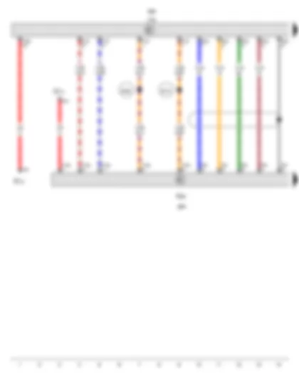
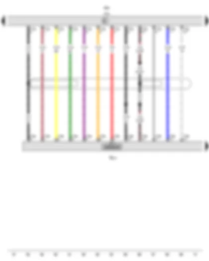
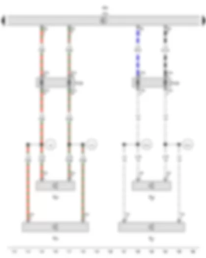
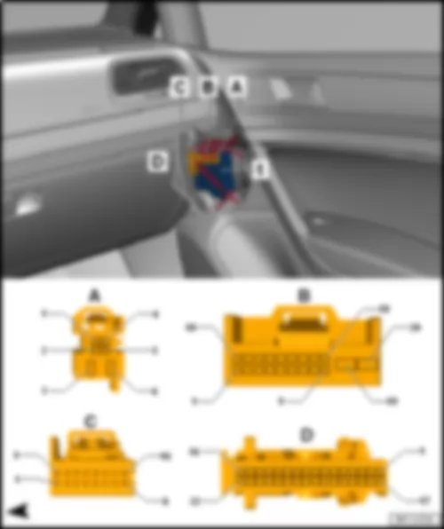
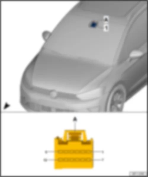
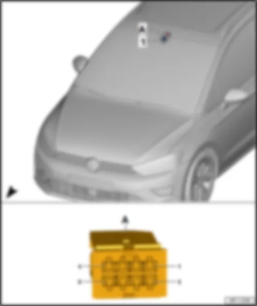
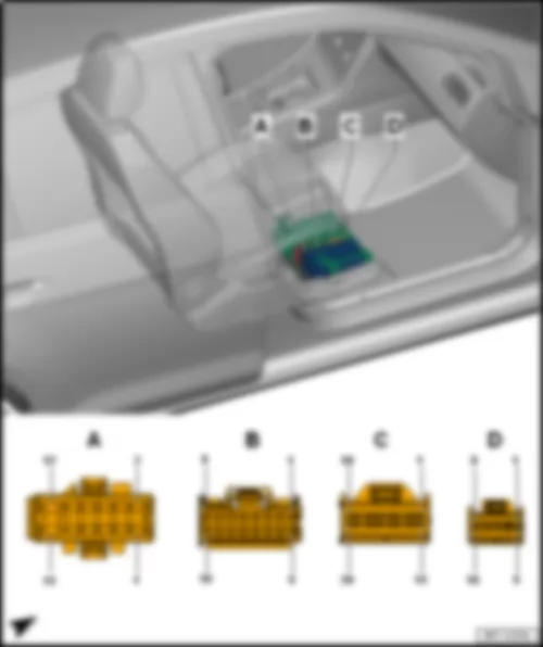
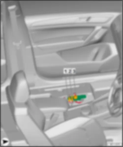
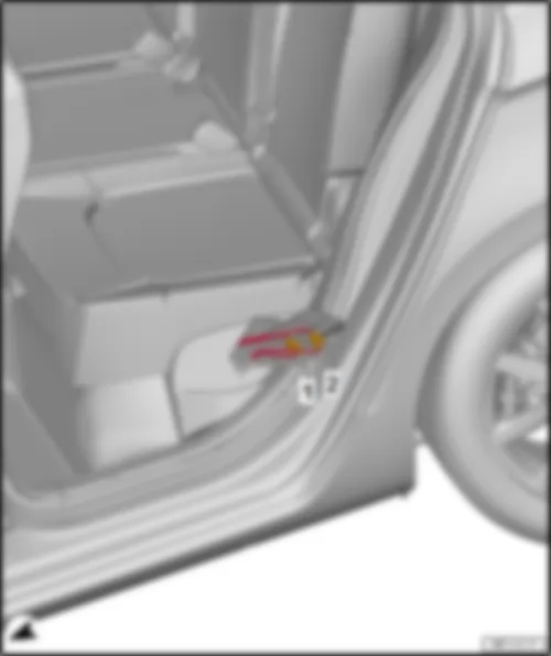
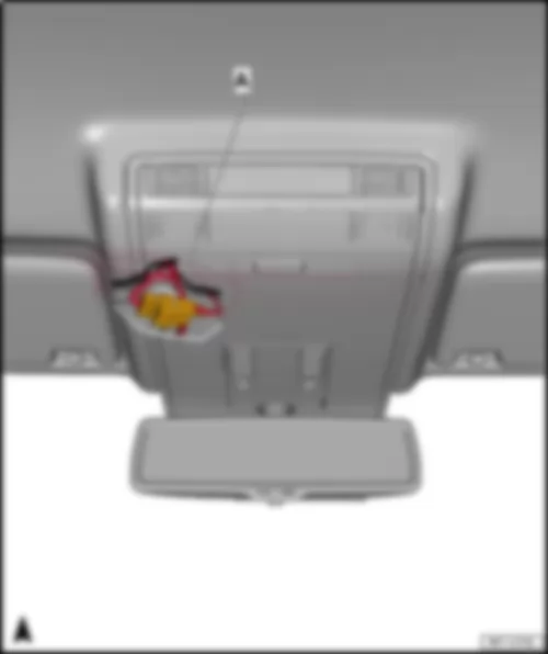
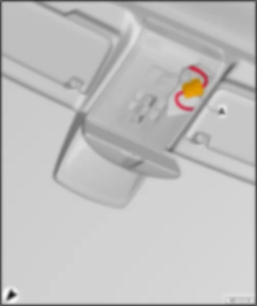
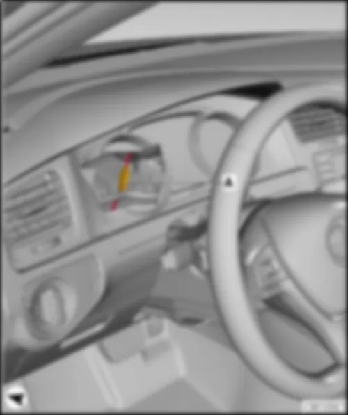
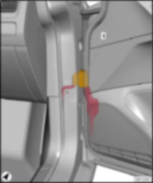
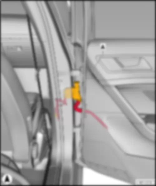
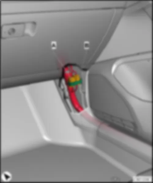
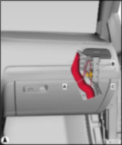
Wiring Diagram VW GOLF SPORTSVAN 2014 - Multimedia system operating unit - Display unit for front information display and operating unit control unit - Control unit 1 for information electronics
| E380 | Multimedia system operating unit |
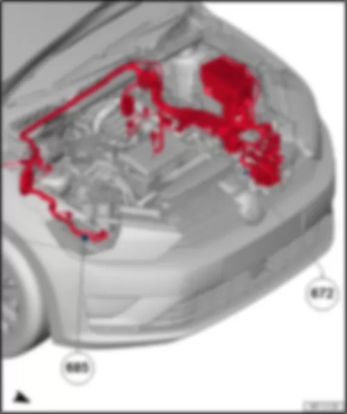
| J685 | Display unit for front information display and operating unit control unit |
| J794 | Control unit 1 for information electronics |
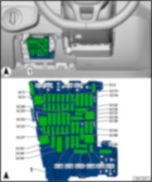
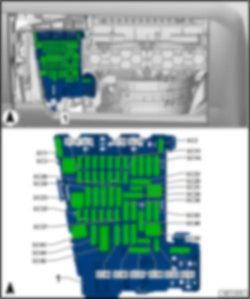
| SC10 | Fuse 10 on fuse holder C |
| SC12 | Fuse 12 on fuse holder C |
| T5m | 5-pin connector, purple |
| T5n | 5-pin connector, white |
| T12b | 12-pin connector, black |
| T12f | 12-pin connector, black |
| T18d | 18-pin connector, black |
| B769 | Connection 2 (CAN bus diagnosis, high), in main wiring harness |
| B779 | Connection 2 (CAN bus diagnosis, low), in main wiring harness |
| * | According to equipment |
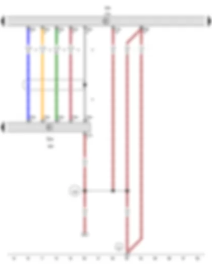
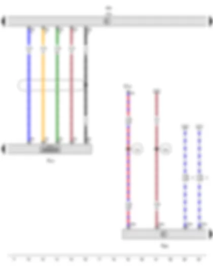
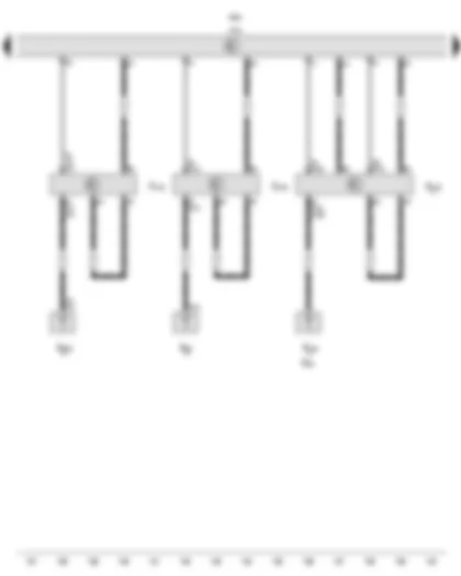
Wiring Diagram VW GOLF SPORTSVAN 2014 - Multimedia system operating unit - Display unit for front information display and operating unit control unit - Control unit 1 for information electronics
| E380 | Multimedia system operating unit |
| J685 | Display unit for front information display and operating unit control unit |
| J794 | Control unit 1 for information electronics |
| T5ab | 5-pin connector, white |
| T5ac | 5-pin connector, purple |
| T12b | 12-pin connector, black |
| T18c | 18-pin connector, black |
| T18d | 18-pin connector, black |
| 256 | Earth connection 2, in radio wiring harness |
| * | According to equipment |
| *2 | From May 2015 |
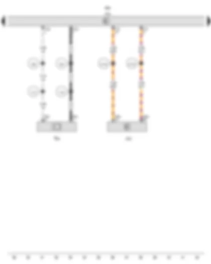
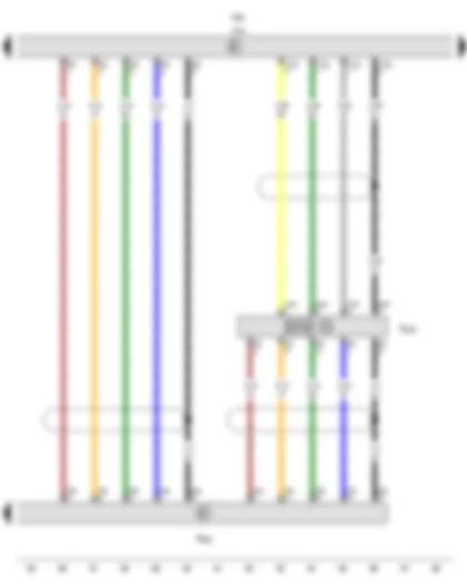
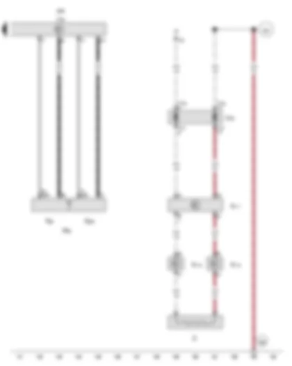
Wiring Diagram VW GOLF SPORTSVAN 2014 - Data bus diagnostic interface - Control unit 1 for information electronics - Telephone microphone
| J533 | Data bus diagnostic interface |
| J685 | Display unit for front information display and operating unit control unit |
| J794 | Control unit 1 for information electronics |
| R38 | Telephone microphone |
| T2bt | 2-pin connector, black |
| T12c | 12-pin connector, blue |
| T12f | 12-pin connector, black |
| T20d | 20-pin connector, red |
| A178 | Connection (infotainment CAN bus, high), in dash panel wiring harness |
| A179 | Connection (infotainment CAN bus, low), in dash panel wiring harness |
| V15 | Connection, in telephone wiring harness |
| V16 | Connection (screening), in telephone wiring harness |
| V54 | Connection 1 (telephone), in main wiring harness |
| V55 | Connection 2 (telephone), in main wiring harness |
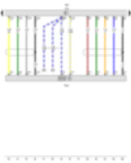
Wiring Diagram VW GOLF SPORTSVAN 2014 - Control unit 1 for information electronics - Connection for external audio sources
| J685 | Display unit for front information display and operating unit control unit |
| J794 | Control unit 1 for information electronics |
| R199 | Connection for external audio sources |
| T1aq | Single connector, grey |
| T4br | 4-pin connector, red |
| T5k | 5-pin connector, yellow |
| T7c | 7-pin connector, white |
| T12e | 12-pin connector, green |
| * | According to equipment |
| *2 | Up to May 2015 |
| *3 | From May 2015 |
Wiring Diagram VW GOLF SPORTSVAN 2014 - Control unit 1 for information electronics - Interface for external multimedia unit
| J685 | Display unit for front information display and operating unit control unit |
| J794 | Control unit 1 for information electronics |
| R215 | Interface for external multimedia unit |
| T12g | 12-pin connector, green |
| T16e | 16-pin connector, brown |
| * | According to equipment |
Wiring Diagram VW GOLF SPORTSVAN 2014 - Control unit 1 for information electronics - Interface for external multimedia unit - USB hub
| J685 | Display unit for front information display and operating unit control unit |
| J794 | Control unit 1 for information electronics |
| R215 | Interface for external multimedia unit |
| R293 | USB hub |
| SC16 | Fuse 16 on fuse holder C |
| T4ap | 4-pin connector, red |
| T5k | 5-pin connector, yellow |
| T5r | 5-pin connector, green |
| 255 | Earth connection 1, in radio wiring harness |
| V32 | Positive connection (30), in telephone wiring harness |
| * | According to equipment |
| *2 | Up to May 2015 |
| *3 | From May 2015 |
Wiring Diagram VW GOLF SPORTSVAN 2014 - Control unit 1 for information electronics - Connection for external audio sources - USB hub
| J685 | Display unit for front information display and operating unit control unit |
| J794 | Control unit 1 for information electronics |
| R199 | Connection for external audio sources |
| R293 | USB hub |
| T4ch | 4-pin connector, black |
| T5k | 5-pin connector, yellow |
| T5p | 5-pin connector, blue |
| T5s | 5-pin connector, green |
| T5t | 5-pin connector, green |
| T12g | 12-pin connector, green |
| * | According to equipment |
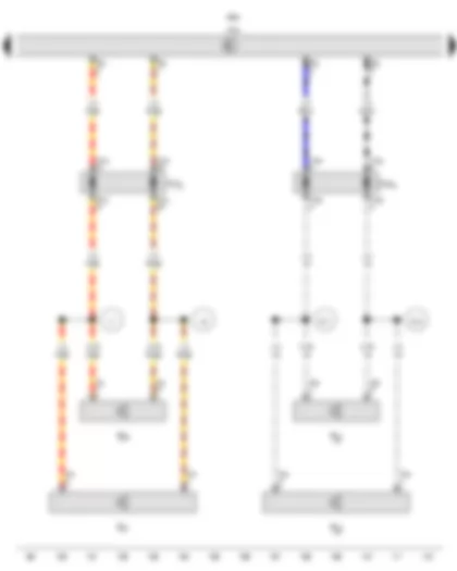
Wiring Diagram VW GOLF SPORTSVAN 2014 - Control unit 1 for information electronics - Rear left treble loudspeaker - Rear left bass loudspeaker - Front left treble loudspeaker - Front left bass loudspeaker
| J685 | Display unit for front information display and operating unit control unit |
| J794 | Control unit 1 for information electronics |
| R14 | Rear left treble loudspeaker |
| R15 | Rear left bass loudspeaker |
| R20 | Front left treble loudspeaker |
| R21 | Front left bass loudspeaker |
| T2a | 2-pin connector, black |
| T2j | 2-pin connector, black |
| T4a | 4-pin connector, black |
| T4k | 4-pin connector, black |
| T8p | 8-pin connector, brown |
| T19a | 19-pin connector, black |
| T19b | 19-pin connector, black |
| T27c | 27-pin connector, black |
| T27d | 27-pin connector, black |
| TTHL | Coupling point on rear left door |
| TTVL | Coupling point on front left door |
| R71 | Connection (positive, loudspeaker)), in rear left door wiring harness |
| R72 | Connection (negative, loudspeaker), in rear left door wiring harness |
| V7 | Connection (positive, front left loudspeaker), in loudspeaker wiring harness |
| V8 | Connection (negative, front left loudspeaker), in loudspeaker wiring harness |
| * | According to equipment |
| *2 | Only models with 8 loudspeakers (8RM) |
Wiring Diagram VW GOLF SPORTSVAN 2014 - Control unit 1 for information electronics - Rear right treble loudspeaker - Rear right bass loudspeaker - Front right treble loudspeaker - Front right bass loudspeaker
| J685 | Display unit for front information display and operating unit control unit |
| J794 | Control unit 1 for information electronics |
| R16 | Rear right treble loudspeaker |
| R17 | Rear right bass loudspeaker |
| R22 | Front right treble loudspeaker |
| R23 | Front right bass loudspeaker |
| T2c | 2-pin connector, black |
| T2h | 2-pin connector, black |
| T4d | 4-pin connector, black |
| T4h | 4-pin connector, black |
| T8p | 8-pin connector, brown |
| T19c | 19-pin connector, black |
| T19d | 19-pin connector, black |
| T27a | 27-pin connector, black |
| T27b | 27-pin connector, black |
| TTHR | Coupling point on rear right door |
| TTVR | Coupling point on front right door |
| R73 | Connection (positive, loudspeaker)), in rear right door wiring harness |
| R74 | Connection (negative, loudspeaker), in rear right door wiring harness |
| V9 | Connection (positive, front right loudspeaker), in loudspeaker wiring harness |
| V10 | Connection (negative, front right loudspeaker), in loudspeaker wiring harness |
| * | According to equipment |
| *2 | Only models with radio navigation system |
| *3 | Only models with 8 loudspeakers (8RM) |
Wiring Diagram VW GOLF SPORTSVAN 2014 - Control unit 1 for information electronics - Radio aerial 2 - Left aerial module - Right aerial module - Digital radio aerial - Radio aerial
| J685 | Display unit for front information display and operating unit control unit |
| J794 | Control unit 1 for information electronics |
| R93 | Radio aerial 2 |
| R108 | Left aerial module |
| R109 | Right aerial module |
| R183 | Digital radio aerial |
| R248 | Radio aerial |
| * | Only models with no digital radio |
| *2 | Rear window aerial |
| *3 | Only models with digital radio |
Wiring Diagram VW GOLF SPORTSVAN 2014 - Control unit 1 for information electronics - Roof aerial - GPS aerial - Amplitude modulation (AM) frequency filter - Frequency modulation (FM) frequency filter in negative wire - Frequency modulation (FM) frequency filter in positive wire - GSM aerial - Heated rear window
| J9 | Heated rear window relay |
| J685 | Display unit for front information display and operating unit control unit |
| J794 | Control unit 1 for information electronics |
| RX5 | Roof aerial |
| R50 | GPS aerial |
| R177 | Amplitude modulation (AM) frequency filter |
| R178 | Frequency modulation (FM) frequency filter in negative wire |
| R179 | Frequency modulation (FM) frequency filter in positive wire |
| R205 | GSM aerial |
| T10f | 10-pin connector, black |
| T10g | 10-pin connector, black |
| THK | Coupling point on rear lid |
| Z1 | Heated rear window |
| 285 | Earth connection 7, in interior wiring harness |
| * | According to equipment |
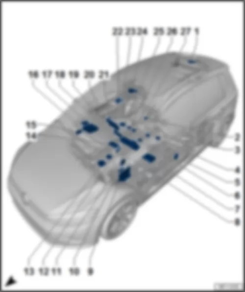
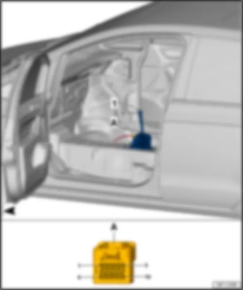
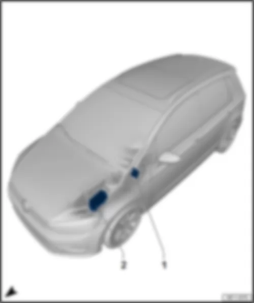
VW GOLF SPORTSVAN 2014 Overview of control units
| q | Fitting locations, models with a diesel engine |
| 25 - | Special vehicle control unit -J608- |
Note
| Only for special vehicles |
| q | Fitting location |
|
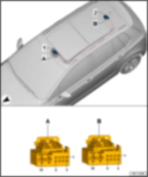
| 1 - | Sliding sunroof adjustment control unit -J245- |
| A - | 10-pin connector -T10b- |
| 2 - | Sunroof roller blind control unit -J394- |
| B - | 10-pin connector -T10a- |
|
| -T10b- (A) | Designation | -T10a- (B) | Designation | |
| 1 | B577 LIN bus connection, in roof wiring harness | 1 | B577 LIN bus connection, in roof wiring harness | |
| 2 | 2 | |||
| 3 | Terminal 30 | 3 | ||
| 4 | Sunroof button -E325- Button 1 for roof roller blind -E584- | 4 | ||
| 5 | Sunroof button -E325- | 5 | Button 1 for roof roller blind -E584- | |
| 6 | Sunroof button -E325- | 6 | ||
| 7 | Sunroof button -E325- | 7 | ||
| 8 | 8 | Terminal 31 | ||
| 9 | Terminal 31 | 9 | Terminal 31 | |
| 10 | Terminal 30 | 10 | Terminal 30 |
|
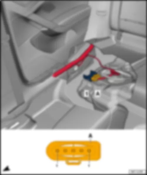
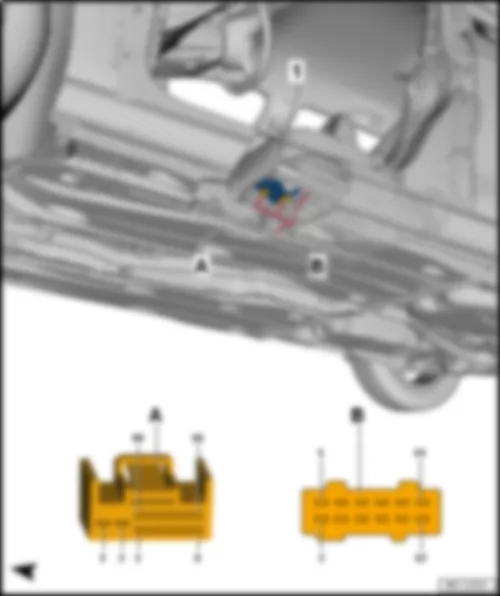
| 1 - | Fuel pump control unit -J538- |
| A - | 5-pin connector -T5v- |
|
| -T5v- (A) | Designation |
| 1 | Fuel system pressurisation pump -G6- |
| 2 | Fuel system pressurisation pump -G6- |
| 3 | Terminal 87 |
| 4 | Terminal 31 |
| 5 | Engine control unit -J623- |
|
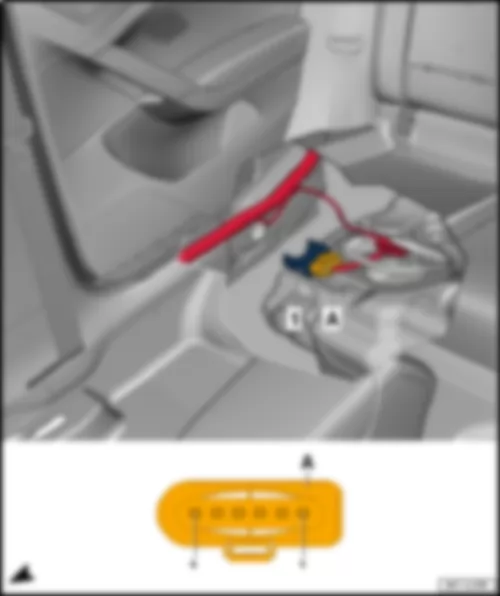
| 1 - | Fuel pump control unit -J538- |
| A - | 6-pin connector -T6u- |
|
| -T6u- (A) | Designation |
| 1 | Fuel system pressurisation pump -G6- |
| 2 | Fuel system pressurisation pump -G6- |
| 3 | Fuel system pressurisation pump -G6- |
| 4 | Terminal 31 |
| 5 | Terminal 87 |
| 6 | Engine control unit -J623- |
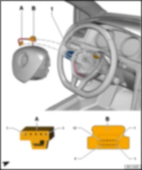
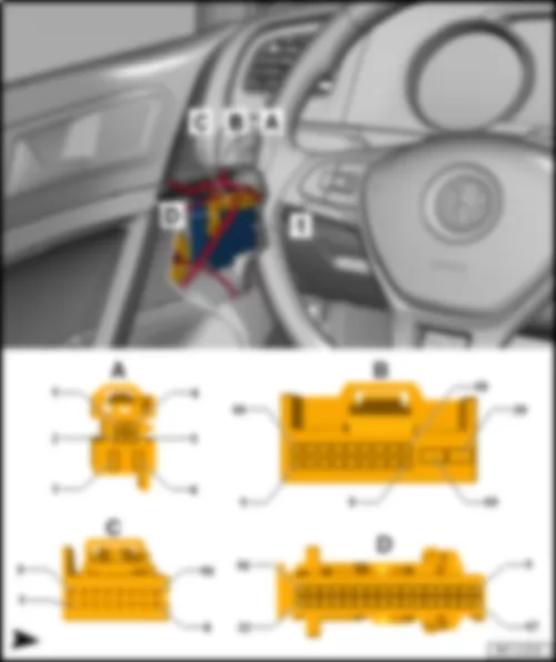
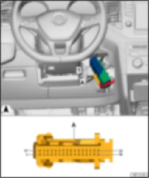
| 1 - | Multifunction steering wheel control unit -J453- |
| A - | 5-pin connector -T5- |
| B - | 12-pin connector -T12k- |
|
| -T5- (A) | Designation | -T12k- (B) | Designation | |
| 1 | Terminal 31 | 1 | ||
| 2 | Terminal 30 | 2 | ||
| 3 | LIN bus | 3 | Driver side airbag igniter -N95- | |
| 4 | 4 | Driver side airbag igniter -N95- | ||
| 5 | 5 | |||
| 6 | ||||
| 7 | Terminal 31 | |||
| 8 | Horn plate -H- | |||
| 9 | LIN bus | |||
| 10 | Terminal 30 | |||
| 11 | ||||
| 12 |
|
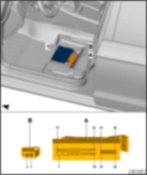
| 1 - | Massage control unit -J740- |
| A - | 16-pin connector -T16i- |
| B - | 12-pin connector -T12i- |
|
| -T16i- (A) | Designation | -T12i- (B) | Designation | |
| 1 | 1 | |||
| 2 | 2 | |||
| 3 | 3 | |||
| 4 | Lumbar support longitudinal adjustment sender -G375-1) Lumbar support height adjustment sender -G374-2) | 4 | ||
| 5 | 5 | |||
| 6 | Lumbar support height adjustment sender -G374-1) Lumbar support longitudinal adjustment sender -G375-2) | 6 | ||
| 7 | Driver seat lumbar support adjustment switch -E176- | 7 | ||
| 8 | Driver seat lumbar support adjustment switch -E176- | 8 | ||
| 9 | Driver seat lumbar support adjustment switch -E176- Massage function button -E337- | 9 | ||
| 10 | 10 | |||
| 11 | Driver seat lumbar support longitudinal adjustment motor -V125-1) Driver seat lumbar support height adjustment motor -V129-2) | 11 | Terminal 30 | |
| 12 | Lumbar support longitudinal adjustment sender -G375- Lumbar support height adjustment sender -G374- | 12 | Terminal 31 | |
| 13 | Driver seat lumbar support longitudinal adjustment motor -V125-1) Driver seat lumbar support height adjustment motor -V129-2) | |||
| 14 | Massage function button -E337- | |||
| 15 | Driver seat lumbar support height adjustment motor -V129-1) Driver seat lumbar support longitudinal adjustment motor -V125-2) | |||
| 16 | Driver seat lumbar support height adjustment motor -V129-1) Driver seat lumbar support longitudinal adjustment motor -V125-2) |
| 1) Only left-hand drive models |
| 2) Only right-hand drive models |
|
| 1 - | Driver door control unit -J386- |
| A - | 6-pin connector -T6o- |
| B - | 20-pin connector -T20a- |
| C - | 16-pin connector -T16a- |
| D - | 32-pin connector -T32a- |
|
| -T6o- (A) | Designation | -T20a- (B) | Designation | -T16a- (C) | Designation | -T32a- (D) | Designation | |||
| 1 | 1 | Driver door contact switch -F2- | 1 | 1 | Central locking SAFE function warning lamp -K133- | |||||
| 2 | 2 | 2 | Driver side automatic anti-dazzle exterior mirror -Y20- | 2 | ||||||
| 3 | Driver side window regulator motor -V147- | 3 | 3 | Driver side turn signal repeater bulb in exterior mirror -L131- | 3 | |||||
| 4 | 4 | 4 | 4 | Terminal 58 | ||||||
| 5 | 5 | Front left central locking actuator -F131- | 5 | Driver side mirror adjustment motor -V17- Driver side mirror adjustment motor -V149- | 5 | Terminal 31 | ||||
| 6 | Driver side window regulator motor -V147- | 6 | Front left central locking actuator -F131- | 6 | 6 | |||||
| 7 | 7 | Driver side automatic anti-dazzle exterior mirror -Y20- | 7 | |||||||
| 8 | Interior mirror -EX5- | 8 | 8 | Light 1 for front left door background lighting -L199- Driver side door interior handle illumination bulb -L146- Light 2 for front left door background lighting -L203- | ||||||
| 9 | 9 | 9 | ||||||||
| 10 | 10 | Driver side fold-in mirror motor -V121- | 10 | |||||||
| 11 | 11 | Heated exterior mirror on driver side -Z4- | 11 | |||||||
| 12 | Driver door central locking motor -V56- | 12 | 12 | |||||||
| 13 | Driver door central locking SAFELOCK function motor -V161- | 13 | 13 | Central locking button -E600- | ||||||
| 14 | B507 Connection (convenience CAN bus, low), in interior wiring harness | 14 | 14 | |||||||
| 15 | B506 Connection (convenience CAN bus, high), in interior wiring harness | 15 | Driver side fold-in mirror motor -V121- | 15 | ||||||
| 16 | 16 | Driver side mirror adjustment motor -V17- | 16 | |||||||
| 17 | Interior mirror -EX5- | 17 | ||||||||
| 18 | 18 | |||||||||
| 19 | Terminal 30 | 19 | ||||||||
| 20 | Terminal 31 | 20 | ||||||||
| 21 | ||||||||||
| 22 | ||||||||||
| 23 | ||||||||||
| 24 | Mirror adjustment switch -E43- Mirror adjustment changeover switch -E48- | |||||||||
| 25 | Adjustment switch for mirror with fold-in feature -E168- | |||||||||
| 26 | ||||||||||
| 27 | ||||||||||
| 28 | Central locking button -E600- | |||||||||
| 29 | ||||||||||
| 30 | ||||||||||
| 31 | Front right window regulator switch in driver door -E81- | |||||||||
| 32 | Front left window regulator switch -E40- |
|
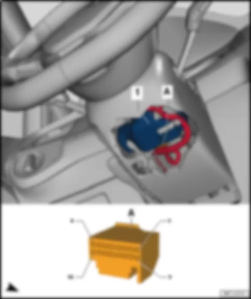
| 1 - | Steering column electronics control unit -J527- |
| A - | 16-pin connector -T16g- , for models with no steering wheel heating |
| A - | 14-pin connector -T14l- , for models with steering wheel heating |
| B - | 4-pin connector -T4as- |
|
| -T16g- (A) | Designation | -T16g- (A) | Designation | -T4as- (B) | Designation | ||
| 1 | Terminal 30 | 9 | 1 | Driver side airbag igniter -N95- | |||
| 2 | Terminal 31 | 10 | 2 | Driver side airbag igniter -N95- | |||
| 3 | B507 Connection (convenience CAN bus, low), in interior wiring harness | 11 | Selector lever -E313- | 3 | |||
| 4 | B506 Connection (convenience CAN bus, high), in interior wiring harness | 12 | 4 | ||||
| 5 | Cruise control system | 13 | |||||
| 6 | Engine control unit -J623- , terminal 50 | 14 | Onboard supply control unit -J519- , terminal 15 | ||||
| 7 | Onboard supply control unit -J519- , terminal S | 15 | |||||
| 8 | B549 Connection 2 (LIN bus) in main wiring harness | 16 | Onboard supply control unit -J519- , terminal 15 |
|
| -T14l- (A) | Designation | -T14l- (B) | Designation | -T4as- (B) | Designation | ||
| 1 | Terminal 30 for steering wheel heating | 8 | Terminal 31 for steering wheel heating | 1 | Driver side airbag igniter -N95- | ||
| 2 | Terminal 30 | 9 | Selector lever -E313- | 2 | Driver side airbag igniter -N95- | ||
| 3 | 10 | Onboard supply control unit -J519- , terminal 15 | 3 | ||||
| 4 | Terminal 31 | 11 | Onboard supply control unit -J519- , terminal 15 | 4 | |||
| 5 | B507 Connection (convenience CAN bus, low), in interior wiring harness | 12 | Onboard supply control unit -J519- , terminal S | ||||
| 6 | B506 Connection (convenience CAN bus, high), in interior wiring harness | 13 | Engine control unit -J623- , terminal 50 | ||||
| 7 | Cruise control system off | 14 | B549 Connection 2 (LIN bus) in main wiring harness |
|
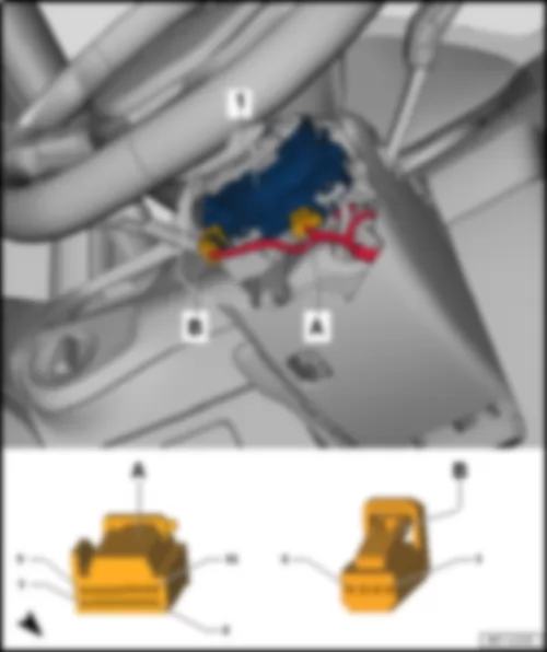
| 1 - | Control unit for electronic steering column lock -J764- |
| A - | 16-pin connector -T16d- |
|
| -T16d- (A) | Designation | -T16d- (A) | Designation | |
| 1 | 9 | |||
| 2 | Terminal 30 | 10 | Terminal 31 | |
| 3 | 11 | |||
| 4 | Starter button -E378- | 12 | Engine control unit -J623- , terminal 50 | |
| 5 | 13 | Starter button -E378- | ||
| 6 | Onboard supply control unit -J519- , terminal 15 | 14 | Selector lever -E313- | |
| 7 | Onboard supply control unit -J519- , terminal S | 15 | B506 Connection (convenience CAN bus, high), in interior wiring harness | |
| 8 | Onboard supply control unit -J519- , terminal 15 | 16 | B507 Connection (convenience CAN bus, low), in interior wiring harness |
|
| 1 - | Digital sound package control unit -J525- |
| A - | 38-pin connector -T38- |
| B - | 2-pin connector -T2ed- |
|
| -T38- (A) | Designation | -T38- (A) | Designation | |
| 1 | Terminal 30 | 20 | Rear right bass loudspeaker -R17- | |
| 2 | Terminal 31 | 21 | Front right bass loudspeaker -R23- | |
| 3 | Front left bass loudspeaker -R21- | 22 | ||
| 4 | Subwoofer -R211- | 23 | ||
| 5 | Subwoofer -R211- | 24 | ||
| 6 | 25 | |||
| 7 | Rear left bass loudspeaker -R15- | 26 | ||
| 8 | Rear right bass loudspeaker -R17- | 27 | ||
| 9 | Front right bass loudspeaker -R23- | 28 | ||
| 10 | 29 | |||
| 11 | Front left treble loudspeaker -R20- | 30 | ||
| 12 | Front left treble loudspeaker -R20- | 31 | Rear left treble loudspeaker -R14- | |
| 13 | Front right treble loudspeaker -R22- | 32 | Rear left treble loudspeaker -R14- | |
| 14 | Front right treble loudspeaker -R22- | 33 | Rear right treble loudspeaker -R16- | |
| 15 | Front left bass loudspeaker -R21- | 34 | Rear right treble loudspeaker -R16- | |
| 16 | Subwoofer -R211- | 35 | ||
| 17 | Subwoofer -R211- | 36 | ||
| 18 | 37 | |||
| 19 | Rear left bass loudspeaker -R15- | 38 |
|
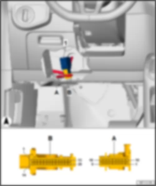
| 1 - | Interface for entry and start system -J965- |
| A - | 32-pin connector -T32d- |
|
| -T32d- (A) | Designation | -T32d– (A) | Designation | |
| 1 | 17 | Terminal 31 | ||
| 2 | 18 | |||
| 3 | Terminal 30 | 19 | Interior aerial 1 for entry and start system -R138- | |
| 4 | 20 | Rear bumper aerial for entry and start system -R136- | ||
| 5 | Front passenger door exterior handle contact sensor -G416- | 21 | Passenger side aerial for entry and start system -R135- | |
| 6 | 22 | Luggage compartment aerial for entry and start system -R137- | ||
| 7 | 23 | Driver side aerial for entry and start system -R134- | ||
| 8 | 24 | Driver side aerial for entry and start system -R134- | ||
| 9 | Driver door exterior handle contact sensor -G415- | 25 | Luggage compartment aerial for entry and start system -R137- | |
| 10 | Onboard supply control unit -J519- | 26 | Passenger side aerial for entry and start system -R135- | |
| 11 | 27 | Rear bumper aerial for entry and start system -R136- | ||
| 12 | 28 | Interior aerial 1 for entry and start system -R138- | ||
| 13 | 29 | |||
| 14 | 30 | Starter button -E378- | ||
| 15 | 31 | |||
| 16 | B407 Connection 2 (convenience CAN bus, low), in main wiring harness | 32 | B398 Connection 2 (convenience CAN bus, high), in main wiring harness |
|
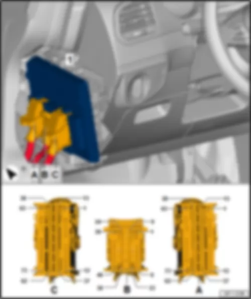
| 1 - | Onboard supply control unit -J519- |
| A - | 73-pin connector -T73a- |
| B - | 46-pin connector -T46a- |
| C - | 73-pin connector -T73b- |
|
| -T73a- (A) | Designation | -T46a- (B) | Designation | -T73b- (C) | Designation | ||
| 1 | Terminal 30 | 1 | Right headlight dipped beam bulb -M31- | 1 | Terminal 30 left light supply | ||
| 2 | Heated seat cushion for driver seat -Z6- | 2 | Right headlight main beam bulb -M32- Right static cornering light -M52- | 2 | |||
| 3 | Tank filler flap release -EX13- - | 3 | 3 | Bulb 2 for rear right turn signal -M81- | |||
| 4 | Tank filler flap release -EX13- + | 4 | Left daytime running light bulb -L174- | 4 | Terminal 15 | ||
| 5 | Heated seat cushion for front passenger seat -Z8- | 5 | Right fog light bulb -L23- Right static cornering light -M52- | 5 | Left headlight dipped beam bulb -M29- | ||
| 6 | Rear right door central locking motor, lock -V215- | 6 | 6 | Left tail light bulb -M4- Right tail light bulb -M2- | |||
| 7 | Rear right door central locking motor, lock -V215- | 7 | Windscreen and rear window washer pump -V59- | 7 | |||
| 8 | 8 | Windscreen and rear window washer pump -V59- | 8 | Right brake and tail light bulb -M22- | |||
| 9 | Rear lid central locking motor -V53- | 9 | Left washer jet heater element -Z20- Right washer jet heater element -Z21- | 9 | Bulb 2 for rear left turn signal -M80- | ||
| 10 | 10 | Front left side marker bulb -M33- | 10 | Left brake and tail light bulb 2 -M58- | |||
| 11 | 11 | Reversing light switch -F4- | 11 | Left reversing light bulb -M16- | |||
| 12 | Term. 31 | 12 | Front right brake pad wear sender -G35- | 12 | Glove compartment light -W6- | ||
| 13 | Terminal 15 voltage supply relay -J329- | 13 | Brake fluid level warning contact -F34- | 13 | |||
| 14 | Terminal 15 voltage supply relay -J329- Signal line | 14 | Bonnet contact switch -F387- | 14 | |||
| 15 | Sliding sunroof adjustment control unit -J245- , LIN bus | 15 | 15 | Light switch -E1- , dipped beam position | |||
| 16 | Convenience CAN bus high | 16 | Coolant shortage indicator sender -G32- | 16 | Light switch -E1- , automatic headlight control position | ||
| 17 | Convenience CAN bus low | 17 | 17 | ||||
| 18 | 18 | 18 | |||||
| 19 | 19 | Ambient temperature sensor -G17- , - Coolant shortage indicator sender -G32- , - Windscreen washer fluid level sender -G33- , - | 19 | Switch and instrument illumination regulator -E20- | |||
| 20 | 20 | Front right turn signal bulb -M7- | 20 | ||||
| 21 | 21 | Right side light bulb -M3- Front right side marker bulb -M34- | 21 | Driving program button -E598- | |||
| 22 | 22 | Front right headlight -MX2- , xenon shutter | 22 | ||||
| 23 | 23 | Front left headlight -MX1- , xenon shutter | 23 | ||||
| 24 | 24 | Horn relay -J413- | 24 | Heated rear window relay -J9- | |||
| 25 | 25 | 25 | |||||
| 26 | 26 | 26 | |||||
| 27 | 27 | Ambient temperature sensor -G17- | 27 | ||||
| 28 | 28 | Windscreen washer fluid level sender -G33- | 28 | Rain and light sensor -G397- Humidity sender -G355- | |||
| 29 | 29 | 29 | |||||
| 30 | Rear right door central locking motor, lock -V215- , safe | 30 | Wiper motor control unit -J400- | 30 | |||
| 31 | Central locking button -E600- | 31 | Anti-theft alarm system horn -H8- | 31 | Rear right turn signal bulb -M8- | ||
| 32 | Rear lid handle release button -E234- | 32 | Right daytime running light bulb -L175- | 32 | Interior monitoring switch -E183- | ||
| 33 | Rear right door contact switch -F11- | 33 | 33 | ||||
| 34 | Rear left door central locking motor, lock -V214- , safe | 34 | 34 | Driving program button -E598- | |||
| 35 | Rear left door contact switch -F10- | 35 | 35 | ||||
| 36 | Rear left door central locking motor, lock -V214- , safe + | 36 | Front left turn signal bulb -M5- | 36 | |||
| 37 | Rear right door central locking motor, lock -V215- , safe + | 37 | 37 | ||||
| 38 | 38 | 38 | |||||
| 39 | 39 | Left headlight main beam bulb -M30- Left static cornering light -M51- | 39 | ||||
| 40 | 40 | Anti-theft alarm system horn -H8- | 40 | Front right seat temperature sender -G345- | |||
| 41 | 41 | 41 | |||||
| 42 | 42 | 42 | Hazard warning light switch -EX3- | ||||
| 43 | Light switch -E1- | 43 | 43 | Front left seat temperature sender -G344- | |||
| 44 | Ignition/starter switch -D- , terminal 15 | 44 | 44 | ||||
| 45 | 45 | Left fog light bulb -L22- Left static cornering light -M51- | 45 | ||||
| 46 | Light switch -E1- , zero position | 46 | Headlight washer system pump -V11- | 46 | |||
| 47 | Ignition/starter switch -D- , terminal 15 | 47 | |||||
| 48 | Rear right door contact switch -F11- | 48 | Indicator lamp for hazard warning light -K6- | ||||
| 49 | Heated rear window button -E230- | 49 | |||||
| 50 | Rear left door contact switch -F10- | 50 | |||||
| 51 | Button for deactivating interior monitoring and vehicle inclination sensor -E616- | 51 | Start/Stop operation button -E693- | ||||
| 52 | Rear lid contact switch for anti-theft alarm -F123- | 52 | |||||
| 53 | Terminal 31 | 53 | |||||
| 54 | Ignition/starter switch -D- , terminal S | 54 | |||||
| 55 | Switch and instrument illumination regulator -E20- | 55 | |||||
| 56 | 56 | Front left seat temperature sender -G344- | |||||
| 57 | High-level brake light bulb -M25- | 57 | |||||
| 58 | 58 | Brake light switch -F- | |||||
| 59 | Left number plate light -X4- Right number plate light -X5- | 59 | |||||
| 60 | Rear left turn signal bulb -M6- | 60 | Start/Stop operation button -E693- | ||||
| 61 | Rear window wiper motor -V12- | 61 | |||||
| 62 | Rear window wiper motor -V12- | 62 | Terminal 58d | ||||
| 63 | Terminal 31 | 63 | Terminal 31 | ||||
| 64 | Right reversing light bulb -M17- | 64 | |||||
| 65 | Right brake and tail light bulb 2 -M59- | 65 | |||||
| 66 | Terminal 30, right light supply | 66 | |||||
| 67 | 67 | Front interior light -WX1- | |||||
| 68 | Rear left door central locking motor, lock -V214- | 68 | |||||
| 69 | Rear left door central locking motor, lock -V214- | 69 | |||||
| 70 | 70 | ||||||
| 71 | Left brake and tail light bulb -M21- | 71 | |||||
| 72 | Rear left fog light bulb -L46- Rear right fog light bulb -L47- | 72 | Front left footwell light -K268- Front right footwell light -K269- | ||||
| 73 | Terminal 30, central locking supply | 73 | Terminal 30 |
|
| 1 - | Parking aid control unit -J446- /park assist steering control unit -J791- |
| A - | 18-pin connector -T18a- |
| B - | 26-pin connector -T26e- |
|
| -T18a- (A) | Designation | -T26e- (B) | Designation | |
| 1 | 1 | |||
| 2 | Front left sender for park assist steering on left side of vehicle -G568-1) | 2 | Front parking aid warning buzzer -H22-2) | |
| 3 | Front centre left parking aid sender -G254- | 3 | Park assist steering button -E581- | |
| 4 | Front right parking aid sender -G252- | 4 | Warning light for park assist steering -K241- | |
| 5 | 5 | |||
| 6 | 6 | Rear left parking aid sender -G203- | ||
| 7 | 7 | Rear centre right parking aid sender -G205- | ||
| 8 | 8 | Rear right park assist steering sender -G717-1) | ||
| 9 | 9 | Rear parking aid warning buzzer -H15-2) | ||
| 10 | Front right parking aid sender -G252- Front centre right parking aid sender -G253- Front centre left parking aid sender -G254- Front left parking aid sender -G255- Front left sender for park assist steering on left side of vehicle -G568-1) Front right sender for park assist steering on right side of vehicle -G569-1) | 10 | Front parking aid warning buzzer -H22-2) | |
| 11 | Front left parking aid sender -G255- | 11 | ||
| 12 | Front centre right parking aid sender -G253- | 12 | ||
| 13 | Front right sender for park assist steering on right side of vehicle -G569-1) | 13 | Terminal 31 | |
| 14 | Front right parking aid sender -G252- Front centre right parking aid sender -G253- Front centre left parking aid sender -G254- Front left parking aid sender -G255- Front left sender for park assist steering on left side of vehicle -G568-1) Front right sender for park assist steering on right side of vehicle -G569-1) | 14 | Terminal 15 | |
| 15 | 15 | Rear parking aid warning buzzer -H15-2) | ||
| 16 | 16 | Parking aid button -E266- | ||
| 17 | 17 | Parking aid warning lamp -K136- | ||
| 18 | 18 | Rear left parking aid sender -G203- Rear centre left parking aid sender -G204- Rear centre right parking aid sender -G205- Rear right parking aid sender -G206- Rear left park assist steering sender -G716-1) Rear right park assist steering sender -G717-1) | ||
| 19 | Rear left park assist steering sender -G716-1) | |||
| 20 | Rear centre left parking aid sender -G204- | |||
| 21 | Rear right parking aid sender -G206- | |||
| 22 | Rear left parking aid sender -G203- Rear centre left parking aid sender -G204- Rear centre right parking aid sender -G205- Rear right parking aid sender -G206- Rear left park assist steering sender -G716-1) Rear right park assist steering sender -G717-1) | |||
| 23 | B664 Connection (running gear sensors CAN bus, low), in main wiring harness | |||
| 24 | B663 Connection (running gear sensors CAN bus, high), in main wiring harness | |||
| 25 | ||||
| 26 |
| 1) Only models with park assist steering |
| 2) According to equipment |
|
| 1 - | Data bus diagnostic interface -J533- |
| A - | 20-pin connector -T20d- |
|
| -T20d- (A) | Designation | -T20d- (A) | Designation | |
| 1 | Terminal 30 | 11 | Terminal 31 | |
| 2 | Terminal 30 | 12 | Terminal 31 | |
| 3 | B698 Connection 3 (LIN bus) in main wiring harness | 13 | B549 Connection 2 (LIN bus) in main wiring harness | |
| 4 | 14 | Terminal 15 | ||
| 5 | B407 Connection 2 (convenience CAN bus, low), in main wiring harness | 15 | B398 Connection 2 (convenience CAN bus, high), in main wiring harness | |
| 6 | B390 Connection 1 (powertrain CAN bus, low), in main wiring harness | 16 | B383 Connection 1 (powertrain CAN bus, high), in main wiring harness | |
| 7 | B109 Connection 1 (CAN bus extended low), in main wiring harness | 17 | B108 Connection 1 (CAN bus extended high), in main wiring harness | |
| 8 | B664 Connection (running gear sensors CAN bus, low), in main wiring harness | 18 | B663 Connection (running gear sensors CAN bus, high), in main wiring harness | |
| 9 | Diagnostic connection -U31- | 19 | Diagnostic connection -U31- | |
| 10 | A179 Connection (infotainment CAN bus, low), in dash panel wiring harness | 20 | A178 Connection (infotainment CAN bus, high), in dash panel wiring harness |
|
| 1 - | Control unit for cornering light and headlight range control -J745- |
| A - | 26-pin connector -T26b- |
|
| -T26b- (A) | Designation | -T26b- (A) | Designation | |||||
| 1 | 14 | |||||||
| 2 | B668 Connection 2 (CAN bus extended high) in main wiring harness 1) B108 Connection 1 (CAN bus extended high) in main wiring harness 1) | 15 | ||||||
| 3 | B669 Connection 2 (CAN bus extended low) in main wiring harness 1) B109 Connection 1 (CAN bus extended low) in main wiring harness 1) | 16 | ||||||
| 4 | C67 Connection (CAN bus high) in headlight wiring harness
| 17 | ||||||
| 5 | C68 Connection (CAN bus low) in headlight wiring harness
| 18 | ||||||
| 6 | 19 | |||||||
| 7 | Rear left vehicle level sender -G76- | 20 | ||||||
| 8 | 21 | |||||||
| 9 | 22 | |||||||
| 10 | Rear left vehicle level sender -G76- | 23 | Terminal 15 | |||||
| 11 | Rear left vehicle level sender -G76- | 24 | Terminal 31 | |||||
| 12 | 25 | |||||||
| 13 | 26 |
| 1) According to equipment |
|
| 1 - | Airbag control unit -J234- |
| A - | 90-pin connector -T90a- |
|
| 1 - | Fresh air blower control unit -J126- |
| A - | 4-pin connector -T4al- |
| B - | 2-pin connector -T2fb- |
|
| -T4dc- (A) | Designation | -T2dq- (B) | Designation | |
| 1 | Terminal 31 | 1 | Fresh air blower -V2- | |
| 2 | 2 | Fresh air blower -V2- | ||
| 3 | Terminal 30 | |||
| 4 | A209 Connection 1 (LIN bus) in dash panel wiring harness |
|
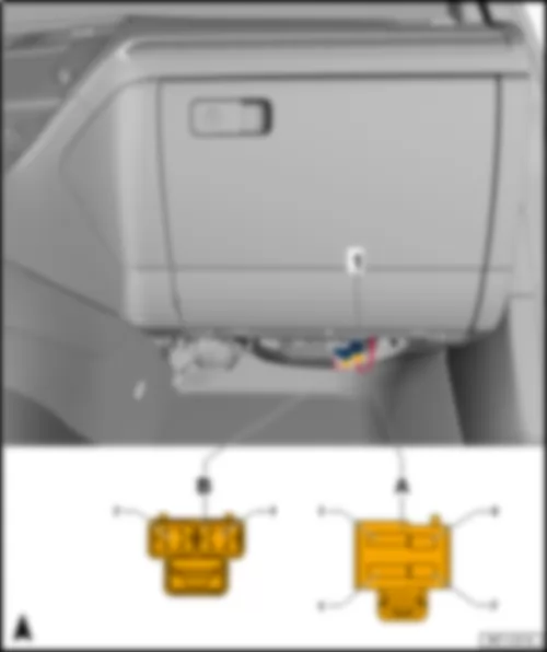
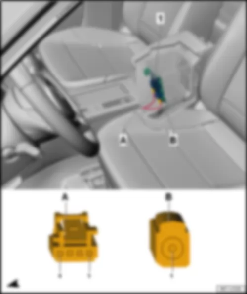
| 1 - | Telephone bracket -R126- |
| A - | 4-pin connector -T4ay- |
| B - | 2-pin connector |
|
| -T4h- (A) | Designation |
| 1 | Terminal 30 |
| 2 | V56 Connection 3 (telephone) in main wiring harness |
| 3 | Control unit 1 for information electronics -J794- |
| 4 | Terminal 31 |
|
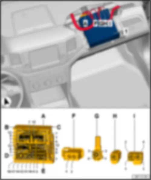
Note
| Multiway connector housing J (chambers: 9-18), made up of connectors K, L, M and N. |
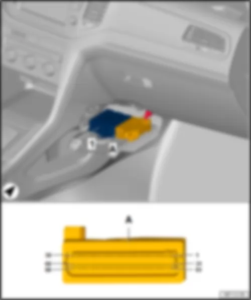
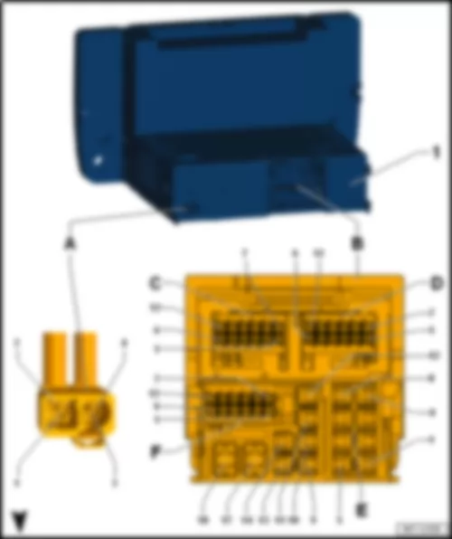
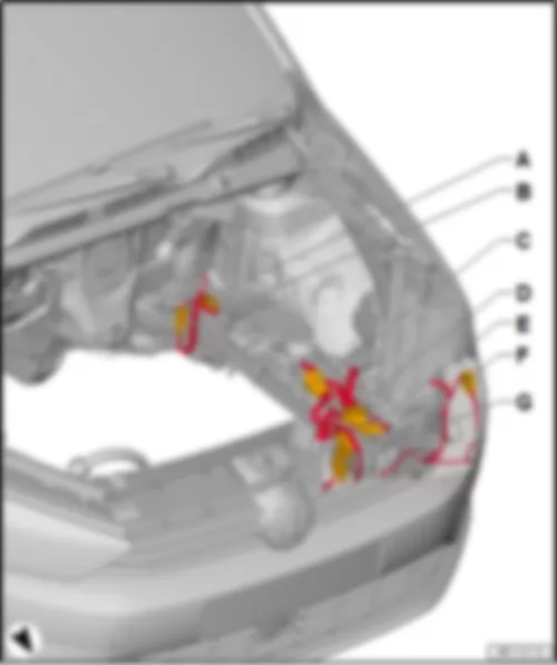
| 1 - | Control unit 1 for information electronics -J794- |
| A - | 8-pin connector -T8aq- |
| B - | 12-pin connector -T12g- |
| C - | 12-pin connector -T12c- |
| D - | 12-pin connector -T12f- |
| E - | 8-pin connector -T8p- |
| F - | 4-pin connector |
| q | TV aerial 1 -R55- |
| q | Radio aerial -R248- |
| G - | Not assigned |
| H - | 5-pin connector -T5k- |
| q | Interface for external multimedia units -R215- |
| q | Connection for external audio sources -R199- |
| q | Chip card reader -D8- |
| I - | 5-pin connector -T5ah- |
| q | Display unit for front information display and operating unit control unit -J685- |
|
| -T8p- (N) | Designation | -T8aq- (J) | Designation | -T2- (O) | Designation | ||
| 1 | Rear right treble loudspeaker -R16- Rear right bass loudspeaker -R17- | 9 | 1 | ||||
| 2 | Front right treble loudspeaker -R22- Front right bass loudspeaker -R23- | 10 | 2 | ||||
| 3 | Front left treble loudspeaker -R20- Front left bass loudspeaker -R21- | 11 | |||||
| 4 | Rear left treble loudspeaker -R14- Rear left bass loudspeaker -R15- | 12 | |||||
| 5 | Rear right treble loudspeaker -R16- Rear right bass loudspeaker -R17- | 13 | |||||
| 6 | Front right treble loudspeaker -R22- Front right bass loudspeaker -R23- | 14 | |||||
| 7 | Front left treble loudspeaker -R20- Front left bass loudspeaker -R21- | 17(1) | Terminal 31 | ||||
| 8 | Rear left treble loudspeaker -R14- Rear left bass loudspeaker -R15- | 18(2) | Terminal 30 |
| -T12f- (M) | Designation | -T12g- (K) | Designation | -T12c- (L) | Designation | ||
| 1 | B769 Connection 2 (diagnostic CAN bus, high), in main wiring harness | 1 | Interface for external multimedia units -R215-1) Connection for external audio sources -R199-1) | 1 | Telephone microphone -R38- | ||
| 2 | Display unit for front information display and operating unit control unit -J685- | 2 | Interface for external multimedia units -R215-1) Connection for external audio sources -R199-1) | 2 | |||
| 3 | 3 | Interface for external multimedia units -R215-1) Connection for external audio sources -R199-1) | 3 | ||||
| 4 | 4 | Interface for external multimedia units -R215-1) Connection for external audio sources -R199-1) | 4 | ||||
| 5 | 5 | Interface for external multimedia units -R215-1) | 5 | ||||
| 6 | A178 Connection (infotainment CAN bus, high), in dash panel wiring harness | 6 | Interface for external multimedia units -R215-1) | 6 | Rear overhead view camera -R246- | ||
| 7 | B799 Connection 4 (diagnosis), in main wiring harness | 7 | Interface for external multimedia units -R215-1) Connection for external audio sources -R199-1) | 7 | Telephone microphone -R38- | ||
| 8 | Display unit for front information display and operating unit control unit -J685- | 8 | Interface for external multimedia units -R215-1) Connection for external audio sources -R199-1) | 8 | |||
| 9 | 9 | Interface for external multimedia units -R215-1) | 9 | ||||
| 10 | 10 | Interface for external multimedia units -R215-1) | 10 | ||||
| 11 | 11 | Interface for external multimedia units -R215-1) | 11 | ||||
| 12 | A179 Connection (infotainment CAN bus, low), in dash panel wiring harness | 12 | Interface for external multimedia units -R215-1) | 12 | Rear overhead view camera -R246- |
| 1) According to equipment |
|
| 1 - | Chip card reader -D8- |
| A - | 2-pin connector -T2- |
| B - | 10-pin connector -T10- |
| C - | 5-pin connector -T5- |
|
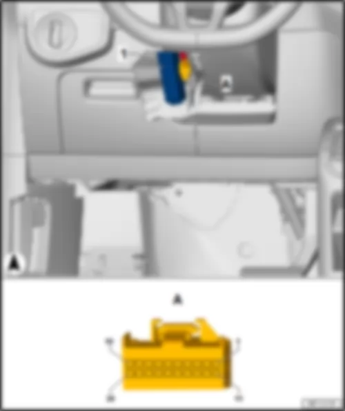
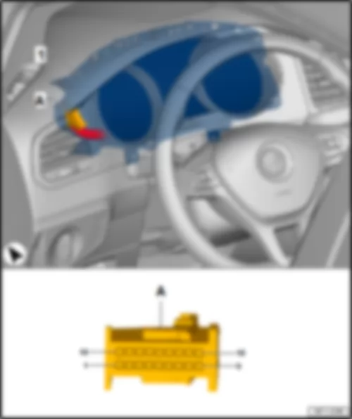
| 1 - | Control unit in dash panel insert -J285- |
| A - | 18-pin connector -T18e- |
|
| -T18e- (A) | Designation | -T18e- (A) | Designation | |
| 1 | Terminal 30 | 10 | Terminal 31 | |
| 2 | 11 | Fuel gauge sender -G- , terminal 31 | ||
| 3 | 12 | Fuel gauge sender 2 -G169- , empty | ||
| 4 | 13 | Fuel gauge sender 2 -G169- , full | ||
| 5 | 14 | Fuel gauge sender -G- , empty | ||
| 6 | 15 | Fuel gauge sender -G- , full | ||
| 7 | 16 | |||
| 8 | Immobiliser reader coil -D2- | 17 | B507 Connection (convenience CAN bus, low), in interior wiring harness | |
| 9 | Immobiliser reader coil -D2- | 18 | B506 Connection (convenience CAN bus, high), in interior wiring harness |
|
| 1 - | Climatronic control unit -J255- |
| A - | 16-pin connector -T16j- |
| B - | 16-pin connector -T16k- |
| C - | 20-pin connector -T20e- |
|
| -T16j- (A) | Designation | -T16k- (B) | Designation | -T20e- (C) | Designation | ||
| 1 | Left temperature flap control motor -V158- | 1 | Potentiometer for defroster flap control motor -G135- Potentiometer for left temperature flap control motor -G220- Potentiometer for right temperature flap control motor -G221- Potentiometer for front air distribution flap control motor -G642- Potentiometer for fresh air/recirculated air, air flow flap control motor -G644- | 1 | Sunlight penetration photosensor -G107- | ||
| 2 | Left temperature flap control motor -V158- | 2 | Potentiometer for left temperature flap control motor -G220- | 2 | |||
| 3 | Defroster flap control motor -V107- | 3 | Potentiometer for right temperature flap control motor -G221- | 3 | Sunlight penetration photosensor -G107- | ||
| 4 | Defroster flap control motor -V107- | 4 | Potentiometer for defroster flap control motor -G135- | 4 | |||
| 5 | Front air distribution flap control motor -V426- | 5 | Potentiometer for front air distribution flap control motor -G642- | 5 | B506 Connection (convenience CAN bus, high), in interior wiring harness | ||
| 6 | Front air distribution flap control motor -V426- | 6 | 6 | B507 Connection (convenience CAN bus, low), in interior wiring harness | |||
| 7 | 7 | Potentiometer for fresh air/recirculated air, air flow flap control motor -G644- | 7 | ||||
| 8 | 8 | Footwell vent temperature sender -G192- | 8 | ||||
| 9 | Fresh air/recirculated air, air flow flap control motor -V425- | 9 | 9 | Sunlight penetration photosensor -G107- | |||
| 10 | Fresh air/recirculated air, air flow flap control motor -V425- | 10 | 10 | ||||
| 11 | Right temperature flap control motor -V159- | 11 | Evaporator temperature sensor -G308- | 11 | |||
| 12 | Right temperature flap control motor -V159- | 12 | 12 | ||||
| 13 | 13 | 13 | Left vent temperature sender -G150- | ||||
| 14 | 14 | Potentiometer for defroster flap control motor -G135- Footwell vent temperature sender -G192- Potentiometer for left temperature flap control motor -G220- Potentiometer for right temperature flap control motor -G221- Evaporator temperature sensor -G308- Potentiometer for front air distribution flap control motor -G642- Potentiometer for fresh air/recirculated air, air flow flap control motor -G644- | 14 | Right vent temperature sender -G151- | |||
| 15 | 15 | 15 | |||||
| 16 | 16 | 16 | A209 Connection 1 (LIN bus) in dash panel wiring harness | ||||
| 17 | Sunlight penetration photosensor -G107- Left vent temperature sender -G150- , Right vent temperature sender -G151- | ||||||
| 18 | Air conditioner compressor regulating valve -N280- | ||||||
| 19 | Terminal 31 | ||||||
| 20 | Terminal 30 |
|
| 1 - | Air conditioning system control unit -J301- |
| A - | 16-pin connector -T16l- |
| B - | 20-pin connector -T20f- |
|
| -T16l- (A) | Designation | -T20f- (B) | Designation | |
| 1 | Potentiometer for temperature flap control motor -G92- Potentiometer for air distribution flap control motor -G645- | 1 | ||
| 2 | 2 | |||
| 3 | 3 | |||
| 4 | 4 | |||
| 5 | Temperature flap control motor -V68- | 5 | B506 Connection (convenience CAN bus, high), in interior wiring harness | |
| 6 | Temperature flap control motor -V68- | 6 | B507 Connection (convenience CAN bus, low), in interior wiring harness | |
| 7 | Air distribution flap control motor -V428- | 7 | ||
| 8 | Air distribution flap control motor -V428- | 8 | ||
| 9 | Air recirculation flap control motor -V113- | 9 | ||
| 10 | Air recirculation flap control motor -V113- | 10 | ||
| 11 | Evaporator temperature sensor -G308- | 11 | ||
| 12 | 12 | |||
| 13 | 13 | |||
| 14 | Potentiometer for temperature flap control motor -G92- Evaporator temperature sensor -G308- Potentiometer for air distribution flap control motor -G645- | 14 | ||
| 15 | 15 | |||
| 16 | 16 | A209 Connection 1 (LIN bus) in dash panel wiring harness | ||
| 17 | ||||
| 18 | Air conditioner compressor regulating valve -N280- | |||
| 19 | Terminal 31 | |||
| 20 | Terminal 30 |
|
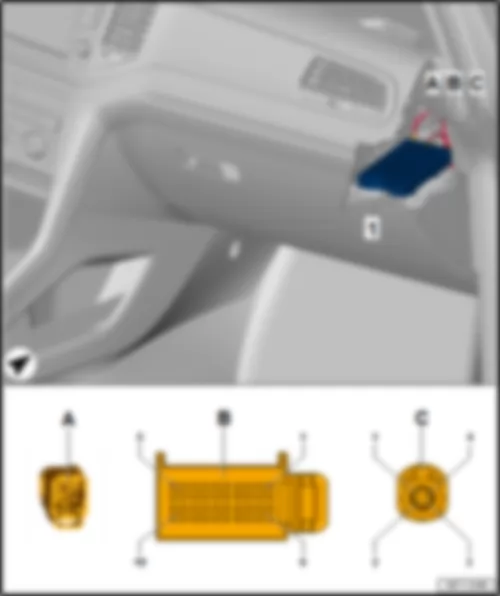
Note
| Multiway connector housing B (chambers: 9-18), made up of connectors C, D, E and F. |
| 1 - | Display unit for front information display and operating unit control unit -J685- |
| A - | 4-pin connector |
| q | Radio aerial -R248- |
| q | Radio aerial 2 -R93- |
| B - | 8-pin connector -T8aq- |
| C - | 12-pin connector -T12ag- |
| D - | 12-pin connector -T12a- |
| E - | 8-pin connector -T8p- |
| F - | 12-pin connector -T12f- |
|
| -T8p- (E) | Designation | -T8aq- (B) | Designation | |
| 1 | Rear right treble loudspeaker -R16- Rear right bass loudspeaker -R17- | 9 | ||
| 2 | Front right treble loudspeaker -R22- Front right bass loudspeaker -R23- | 10 | ||
| 3 | Front left treble loudspeaker -R20- Front left bass loudspeaker -R21- | 11 | ||
| 4 | Rear left treble loudspeaker -R14- Rear left bass loudspeaker -R15- | 12 | ||
| 5 | Rear right treble loudspeaker -R16- Rear right bass loudspeaker -R17- | 13 | ||
| 6 | Front right treble loudspeaker -R22- Front right bass loudspeaker -R23- | 14 | ||
| 7 | Front left treble loudspeaker -R20- Front left bass loudspeaker -R21- | 17(1) | Terminal 31 | |
| 8 | Rear left treble loudspeaker -R14- Rear left bass loudspeaker -R15- | 18(2) | Terminal 30 |
| -T12f- (F) | Designation | -T12ag- (C) | Designation | -T12a- (D) | Designation | ||
| 1 | 1 | 1 | |||||
| 2 | 2 | 2 | |||||
| 3 | 3 | 3 | |||||
| 4 | 4 | 4 | |||||
| 5 | 5 | 5 | |||||
| 6 | A178 Connection (infotainment CAN bus, high), in dash panel wiring harness | 6 | 6 | ||||
| 7 | 7 | 7 | |||||
| 8 | 8 | 8 | |||||
| 9 | 9 | 9 | |||||
| 10 | 10 | 10 | |||||
| 11 | 11 | 11 | |||||
| 12 | A179 Connection (infotainment CAN bus, low), in dash panel wiring harness | 12 | 12 |
|
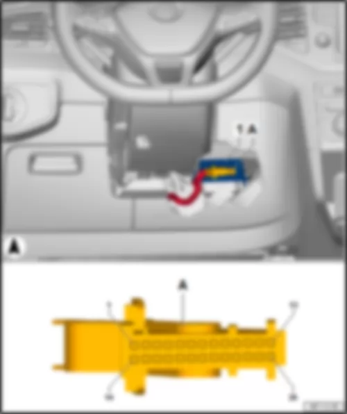
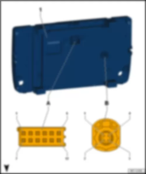
| 1 - | Display unit for front information display and operating unit control unit -J685- |
| A - | 12-pin connector -T12b- |
| B - | 5-pin connector -T5n- |
|
| -T12b- (A) | Designation |
| 1 | Terminal 30 |
| 2 | |
| 3 | A178 Connection (infotainment CAN bus, high), in dash panel wiring harness |
| 4 | |
| 5 | Control unit 1 for information electronics -J794- |
| 6 | |
| 7 | Terminal 31 |
| 8 | |
| 9 | A179 Connection (infotainment CAN bus, low), in dash panel wiring harness |
| 10 | |
| 11 | Control unit 1 for information electronics -J794- |
| 12 |
|
| 1 - | Front passenger door control unit -J387- |
| A - | 6-pin connector -T6ah- |
| B - | 20-pin connector -T20b- |
| C - | 16-pin connector -T16l- |
| D - | 32-pin connector -T32b- |
|
| -T6ah- (A) | Designation | -T20b- (B) | Designation | -T16l- (C) | Designation | -T32b- (D) | Designation | |||
| 1 | 1 | 1 | Front passenger side entry light in exterior mirror -W53- | 1 | ||||||
| 2 | 2 | 2 | 2 | |||||||
| 3 | Front passenger side window regulator motor -V148- | 3 | 3 | Front passenger side turn signal repeater bulb -L132- Heated exterior mirror on front passenger side -Z5- | 3 | Light for passenger door ambient lighting -W87- | ||||
| 4 | 4 | 4 | Front passenger side mirror adjustment motor -V25- Front passenger side mirror adjustment motor -V150- | 4 | Terminal 58 | |||||
| 5 | 5 | Front passenger door contact switch -F3- | 5 | Front passenger side mirror adjustment motor -V25- Front passenger side mirror adjustment motor -V150- | 5 | Terminal 31 | ||||
| 6 | Front passenger side window regulator motor -V148- | 6 | Front passenger door central locking actuator for SAFELOCK function -F244- | 6 | 6 | |||||
| 7 | 7 | Front passenger side mirror adjustment motor -V25- | 7 | |||||||
| 8 | Interior mirror -EX5- | 8 | Front passenger side mirror adjustment motor -V150- | 8 | Light for passenger door ambient lighting -W87- | |||||
| 9 | 9 | Front passenger side fold-in mirror motor -V122- | 9 | |||||||
| 10 | Rear right window regulator motor -V27- | 10 | Front passenger side fold-in mirror motor -V122- | 10 | ||||||
| 11 | Front passenger door central locking motor -V57- Front passenger door central locking SAFELOCK function motor -V162- | 11 | Front passenger side turn signal repeater bulb -L132- | 11 | ||||||
| 12 | Front passenger door central locking SAFELOCK function motor -V162- | 12 | 12 | |||||||
| 13 | Front passenger door central locking motor -V57- | 13 | Front passenger side mirror adjustment motor -V25- | 13 | Central locking button -E600- | |||||
| 14 | B407 Connection 2 (convenience CAN bus, low), in main wiring harness | 14 | Front passenger side mirror adjustment motor -V25- Front passenger side mirror adjustment motor -V150- | 14 | ||||||
| 15 | B398 Connection 2 (convenience CAN bus, high), in main wiring harness | 15 | Heated exterior mirror on front passenger side -Z5- | 15 | ||||||
| 16 | 16 | Front passenger side mirror adjustment motor -V150- | 16 | |||||||
| 17 | Interior mirror -EX5- | 17 | ||||||||
| 18 | 18 | |||||||||
| 19 | Terminal 30 | 19 | ||||||||
| 20 | Terminal 31 | 20 | ||||||||
| 21 | ||||||||||
| 22 | ||||||||||
| 23 | ||||||||||
| 24 | ||||||||||
| 25 | ||||||||||
| 26 | ||||||||||
| 27 | ||||||||||
| 28 | Central locking button -E600- | |||||||||
| 29 | ||||||||||
| 30 | ||||||||||
| 31 | ||||||||||
| 32 | Front passenger side window regulator button -E716- |
|
| 1 - | Front camera for driver assist systems -R242- |
| A - | 12-pin connector -T12a- |
|
| -T12a- (A) | Designation |
| 1 | Adaptive cruise control unit -J428- |
| 2 | B109 Connection 1 (CAN bus extended low), in main wiring harness |
| 3 | |
| 4 | Windscreen heater for front sensors -Z113- |
| 5 | Terminal 31 |
| 6 | Terminal 15 |
| 7 | Adaptive cruise control unit -J428- |
| 8 | B108 Connection 1 (CAN bus extended high), in main wiring harness |
| 9 | |
| 10 | |
| 11 | |
| 12 |
|
| 1 - | Main beam assist control unit -J844- |
| A - | 8-pin connector -T8n- |
|
| -T8bg- (A) | Designation |
| 1 | Terminal 15 |
| 2 | Terminal 31 |
| 3 | B108 Connection 1 (CAN bus extended high), in main wiring harness |
| 4 | |
| 5 | |
| 6 | Front interior light -WX1- |
| 7 | |
| 8 | B109 Connection 1 (CAN bus extended low), in main wiring harness |
| 1) Only models with automatic anti-dazzle exterior mirror |
|
| 1 - | Special vehicle control unit -J608- |
| A - | 12-pin connector -T12l- |
| B - | 16-pin connector -T16m- |
| C - | 20-pin connector -T20g- |
| D - | 16-pin connector -T16n- |
|
| 1 - | Selector lever -E313- |
| A - | 10-pin connector -T10s- |
|
| -T10s- (A) | Designation |
| 1 | Terminal 31 |
| Steering column electronics control unit -J527- | |
| 3 | Terminal 58 |
| 4 | |
| 5 | Terminal 58 |
| 6 | |
| 7 | B383 Connection 1 (powertrain CAN bus, high), in main wiring harness |
| 8 | B390 Connection 1 (powertrain CAN bus, low), in main wiring harness |
| 9 | Terminal 15 |
| 10 | Terminal 30 |
|
| 1 - | Control unit for electronic steering column lock -J764- |
| A - | 16-pin connector -T16d- |
|
| -T16d- (A) | Designation | -T16d- (A) | Designation | |
| 1 | 9 | |||
| 2 | Terminal 30 | 10 | Terminal 31 | |
| 3 | 11 | |||
| 4 | Starter button -E378- | 12 | Engine control unit -J623- , terminal 50 | |
| 5 | 13 | Starter button -E378- | ||
| 6 | Onboard supply control unit -J519- , terminal 15 | 14 | Selector lever -E313- | |
| 7 | Onboard supply control unit -J519- , terminal S | 15 | B507 Connection (convenience CAN bus, low), in interior wiring harness | |
| 8 | Onboard supply control unit -J519- , terminal 15 | 16 | B506 Connection (convenience CAN bus, high), in interior wiring harness |
|
 Deutsch
 English
 English
 Español
 Français
 Nederlands
 Русский

