
WIRING DIAGRAM - A-BUS SERIAL LINE - Alfa Romeo 159 1.9 JTD 16V Fino a 12/05
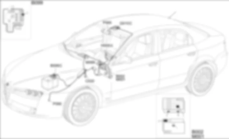
COMPONENTS - A-BUS SERIAL LINE - Alfa Romeo 159 1.9 JTD 16V Fino a 12/05
| Component code | Description | Reference to operation |
| B002 | JUNCTION UNIT UNDER DASHBOARD | |
| B099 | MAXIFUSE BOX ON BATTERY | |
| C020 | PASSENGER SIDE DASHBOARD EARTH | - |
| H005 | STEERING COLUMN SWITCH UNIT | |
| G010 | FRONT COURTESY LIGHT | |
| M001 | BODY COMPUTER | |
| M089 | STEERING LOCK CONTROL UNIT (NBS) | |
| P065 | ELECTRO-CHROMIC INTERIOR REAR VIEW MIRROR | - |
| P090 | ALARM SIREN | - |
COMPONENT LOCATION - A-BUS SERIAL LINE - Alfa Romeo 159 1.9 JTD 16V Fino a 12/05
| Component code | Description | Reference to operation |
| B002 | JUNCTION UNIT UNDER DASHBOARD | |
| B099 | MAXIFUSE BOX ON BATTERY | |
| C020 | PASSENGER SIDE DASHBOARD EARTH | - |
| H005 | STEERING COLUMN SWITCH UNIT | |
| G010 | FRONT COURTESY LIGHT | |
| M001 | BODY COMPUTER | |
| M089 | STEERING LOCK CONTROL UNIT (NBS) | |
| P065 | ELECTRO-CHROMIC INTERIOR REAR VIEW MIRROR | - |
| P090 | ALARM SIREN | - |
DESCRIPTION - A-BUS SERIAL LINE - Alfa Romeo 159 1.9 JTD 16V Fino a 12/05
This vehicle is equipped with a CAN (Controller Area Network) system of electrical connections.The different electronic units that make up the system, known as network "Nodes" are connected to the CAN; the main element of the network is the Body Computer.The various electronic units process the various signals coming from the corresponding sensors both for their own management and for other control units to which they are sent via the CAN.The structure consists of two CAN communication networks which connect nodes belonging to two different areas:- C-CAN for dynamic vehicle control (high speed): bus CAN-H and CAN-L;- B-CAN for the management of standard body functions (low speed): bus CAN-A and CAN-B;the two CAN communication networks are connected to one another by a gateway for transferring joint information, located in the Body Computer Node.A special A-BUS ISO 5 serial line manages the connection with the following functions:- alarm (siren and volumetric/anti-tilt sensors);- automatic wiping (rain senosr);- automatic lighting (dusk sensor).
FUNCTIONAL DESCRIPTION - A-BUS SERIAL LINE - Alfa Romeo 159 1.9 JTD 16V Fino a 12/05
The Body Computer M1 is supplied directly from the battery via line protected by maxifuse F1 of engine compartment control unit B1 at pin 18 of connector F that interfaces with underfacia control unit B2 .The Body Computer M1 receives an ignition-operated supply (INT) at pin 9 of connector F of the interface with the junction unit under the dashboard B2 : this signal is used, amongst other things, to "wake up the network".Pins 8 and 9 of connector I of M1 are earthed.The A-BUS serial line is connected from pin 25 of connector B of the Body Computer M1 with the alarm sensor P90 - pin 2 - and with th steering column switch unit H5 - pin 2 of connector A; the latter manages the signal from the rain sensor.The A-BUS serial line is connected from pin 7 of connector D of the Body Computer M1 with the volumetric/anti-tilt sensors, located in the courtesy light G10 - connector C - pin 4 - and with the rain and dusk sensors, incorporated in the electro-chromic interior rear view mirror P65, pin 3.
 Deutsch
 English
 English
 Español
 Français
 Nederlands
 Русский


