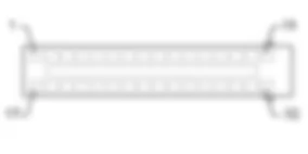
Wiring diagram - DIAGNOSTIC MULTIPLE CONNECTOR - Alfa Romeo GT 2.0 JTS
Components - DIAGNOSTIC MULTIPLE CONNECTOR - Alfa Romeo GT 2.0 JTS
| Component code | Name | Assembly reference |
| B1 | JUNCTION UNIT | - |
| B1 | JUNCTION UNIT | |
| B2 | JUNCTION UNIT UNDER DASHBOARD | |
| B5 | MAXI FUSE-1 BOX | - |
| B99 | MAXIFUSE BOX ON BATTERY | |
| C15 | FACIA EARTH, DRIVER''S SIDE | - |
| F10 | LEFT HEADLAMP ( FRONT ) | |
| F11 | RIGHT HEADLAMP | |
| H1 | IGNITION SWITCH | |
| M1 | BODY COMPUTER | |
| M10 | ENGINE MANAGEMENT ECU | 1056B |
| M10 | ENGINE MANAGEMENT ECU | |
| M50 | ABS CONTROL UNIT ( FRONT ) | |
| M54 | SELESPEED TRANSMISSION CONTROL UNIT | 2127E |
| M60 | AIR BAG CONTROL UNIT |
Location of components - DIAGNOSTIC MULTIPLE CONNECTOR - Alfa Romeo GT 2.0 JTS
Components - DIAGNOSTIC MULTIPLE CONNECTOR - Alfa Romeo GT 2.0 JTS
| Component code | Name | Assembly reference |
| B1 | JUNCTION UNIT | - |
| B1 | JUNCTION UNIT | |
| B2 | JUNCTION UNIT UNDER DASHBOARD | |
| B5 | MAXI FUSE-1 BOX | - |
| B99 | MAXIFUSE BOX ON BATTERY | |
| C15 | FACIA EARTH, DRIVER''S SIDE | - |
| F10 | LEFT HEADLAMP ( FRONT ) | |
| F11 | RIGHT HEADLAMP | |
| H1 | IGNITION SWITCH | |
| M1 | BODY COMPUTER | |
| M10 | ENGINE MANAGEMENT ECU | 1056B |
| M10 | ENGINE MANAGEMENT ECU | |
| M50 | ABS CONTROL UNIT ( FRONT ) | |
| M54 | SELESPEED TRANSMISSION CONTROL UNIT | 2127E |
| M60 | AIR BAG CONTROL UNIT |
Description - DIAGNOSTIC MULTIPLE CONNECTOR - Alfa Romeo GT 2.0 JTS
The car is equipped with numerous self-diagnostic electronic control units.When a tester (Examiner or other instrument) is connected to the control units, self-diagnostic data can be read (parameters, errors) or active testing can be carried out.All tester lines are connected to the EOBD (European On Board Diagnosis) connector in line with EC directive 98/69 - ISO standard J1962, centralised on the Body Computer - connector G.Nodes conected to the network are connected via the B-CAN while the vehicle dynamic control network is tested via special K lines.
Functional description - DIAGNOSTIC MULTIPLE CONNECTOR - Alfa Romeo GT 2.0 JTS
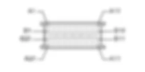
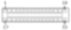
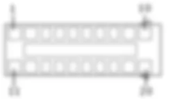
The centralised EOBD tester connector is built into Body ComputerM1 - connector G. It is supplied directly at pin 16 from a line from fuse F39 of underfacia control unitB2; pins 4 and 5 are earthed.Pin 1 is connected by line K to the ABS control unitM50 See E7020 ABS Pin 3 is connected by line K to the Air Bag control unitM60Pin 7 is connected to the engine management control unit M10 via a K line or . Pin 7 is also connected to the SELESPEED control unit M54 . If fitted, the gas discharge headlamp control units F10 and F11 are connected to pin 12. Pins 6 and 14 are connected to the B-CAN network. Underfacia control unitB2, instrument panel E50, door control unit H44, radio (or built in radio-telephone-navigator) P20 and climate control ECU M70 are monitored and ''diagnosed'' via this network. Pins 2 and 10 are supplied for testing via the C-CAN network, which is not used in this version.
 Deutsch
 English
 English
 Español
 Français
 Nederlands
 Русский

