AUTOMOTIVE ELECTRICIANS PORTAL

STARTING/CHARGING – Acura RDX 2013 – SYSTEM WIRING DIAGRAMS

STARTING/CHARGING

Charging Wiring Diagram for Acura RDX 2013

Charging Wiring Diagram for Acura RDX 2013 https://portal-diagnostov.com/license.html
https://portal-diagnostov.com/license.html Automotive Electricians Portal FZCO Automotive Electricians Portal FZCO
Download PDF file

List of elements for Charging Wiring Diagram for Acura RDX 2013:

  • A10
  • A19
  • A20
  • Alternator
  • Battery
  • Battery sensor
  • C11
  • C12
  • C139
  • C14
  • C19
  • Center junction box 2
  • Charging system indicator
  • Computer data lines system
  • Controller
  • D17
  • D18
  • D19
  • Drive circuit indicator
  • Driver's junction box
  • Eld
  • Engine start/ stop switch
  • F-can h
  • F-can l
  • Fuse 1-1 120a
  • Fuse 10a
  • Fuse 15a
  • Fuse 2-3 60a
  • Fuse 2-4 50a
  • Fuse 7.5a
  • G1 (left front of engine compt)
  • G302 (below air filter assembly)
  • G502 (near steering column)
  • G506 (behind center of dash)
  • Gauge control module
  • H10
  • Hot in on or start
  • J/c c009
  • J/c c014 (top right of engine)
  • Micu
  • Multi-information display
  • Power control unit (right side of steering column)
  • Powertrain control module (pcm) (right side of engine compt)
  • Q16
  • Red
  • Starting circuit
  • T101
  • Transceiver f-can
  • Under-dash fuse/relay box (behind left side of dash)
  • Under-hood fuse/relay box (left rear of engine compt)

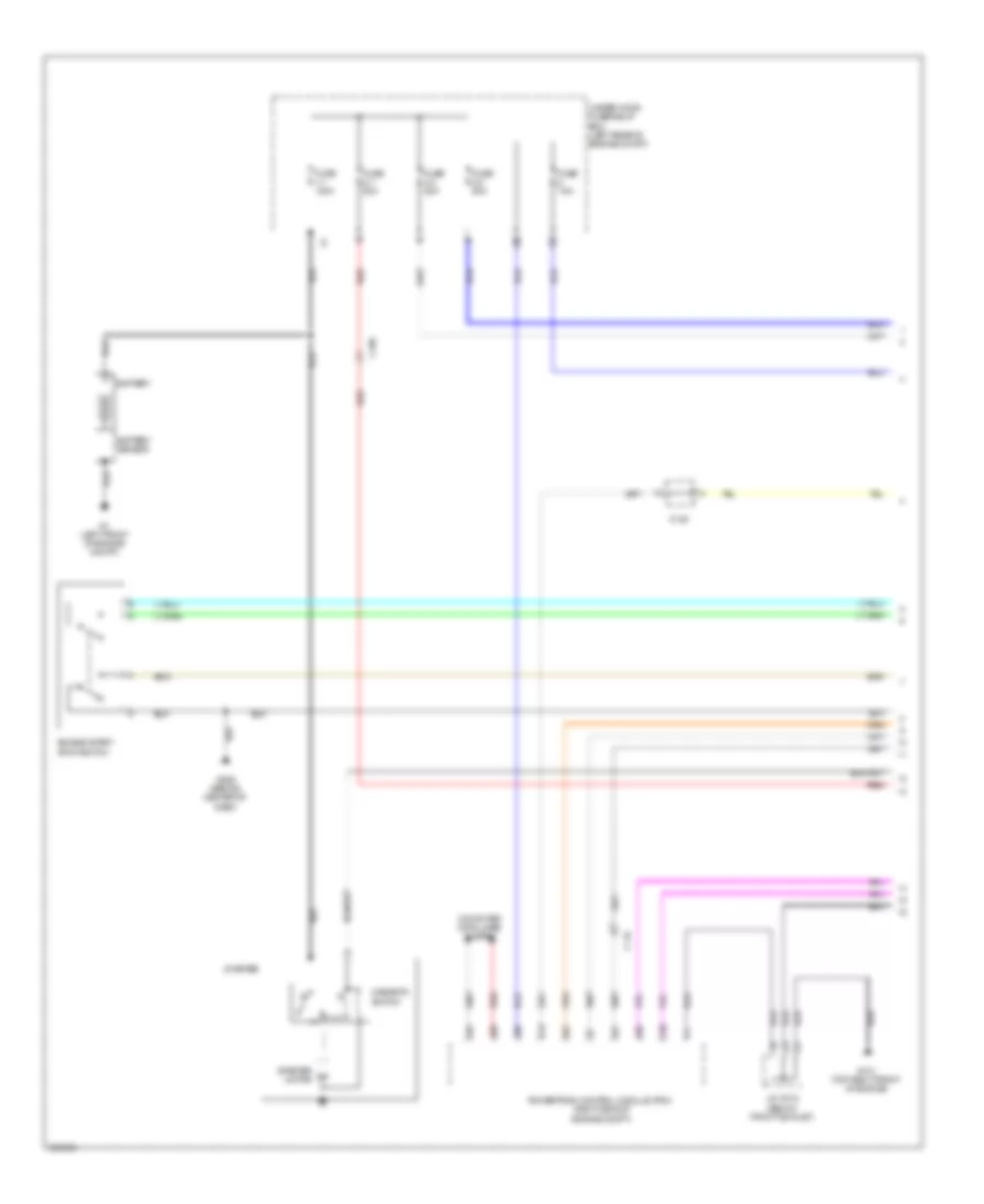
Starting Wiring Diagram (1 of 2) for Acura RDX 2013

Starting Wiring Diagram (1 of 2) for Acura RDX 2013 https://portal-diagnostov.com/license.html
https://portal-diagnostov.com/license.html Automotive Electricians Portal FZCO Automotive Electricians Portal FZCO
Hanki pääsy kaikkiin auton kytkentäkaavioihinDownload PDF file

List of elements for Starting Wiring Diagram (1 of 2) for Acura RDX 2013:

  • A19
  • A20
  • A26
  • A38
  • A41
  • A42
  • B13
  • Battery
  • Battery sensor
  • C109
  • C114
  • C139
  • C36
  • Computer data lines system
  • Engine start/ stop switch
  • Fuse 1-1 120a
  • Fuse 2-1 50a
  • Fuse 2-3 60a
  • Fuse 2-4 50a
  • Fuse 7.5a
  • G1 (left front of engine compt)
  • G101 (top right front of engine)
  • G506 (behind center of dash)
  • J/c c015 (below throttle inlet)
  • Magnetic switch
  • Powertrain control module (pcm) (right side of engine compt)
  • Red
  • Starter
  • Starter motor
  • Under-hood fuse/relay box (left rear of engine compt)

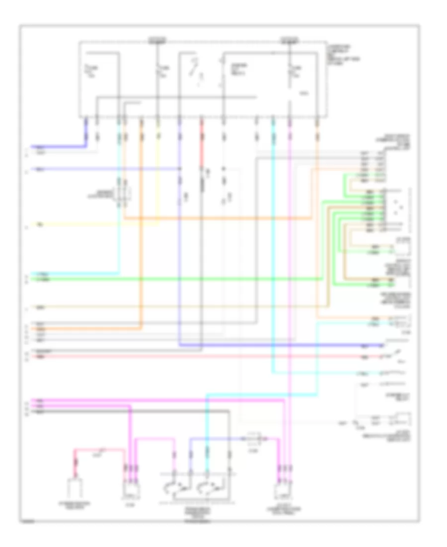
Starting Wiring Diagram (2 of 2) for Acura RDX 2013

Starting Wiring Diagram (2 of 2) for Acura RDX 2013 https://portal-diagnostov.com/license.html
https://portal-diagnostov.com/license.html Automotive Electricians Portal FZCO Automotive Electricians Portal FZCO
Hanki pääsy kaikkiin auton kytkentäkaavioihinDownload PDF file

List of elements for Starting Wiring Diagram (2 of 2) for Acura RDX 2013:

  • (right side of steering column) power control unit
  • A/t gear position indicator
  • Backup control unit (behind left side of dash)
  • C106
  • C107
  • C109
  • C11
  • C12
  • C125
  • C13
  • C138
  • C139
  • C19
  • C20
  • C34
  • D22
  • D32
  • Driver's junction box
  • Fuse 10a
  • Fuse 15a
  • Fuse 7.5a
  • H10
  • Hot in on or start
  • J/c c001 (below multi-information display unit)
  • J/c c009
  • J/c c017 (under right side cowl panel)
  • Keyless access control unit (above steering column)
  • Micu
  • Pnk
  • Red
  • Starter cut relay 1
  • Starter cut relay 2
  • Transmission range switch (top of transmission)
  • Under-dash fuse/relay box (behind left side of dash)