STARTING/CHARGING
2.0L TURBO
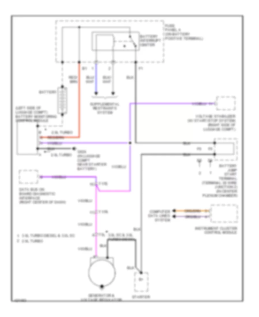
2.0L Turbo, Charging Wiring Diagram for Audi Q5 Premium 2014

List of elements for 2.0L Turbo, Charging Wiring Diagram for Audi Q5 Premium 2014:
- (left side of luggage compt) battery monitoring control module
- 2.0l turbo
- 3.0l sc & 3.0l turbo diesel
- 3.0l turbo diesel & 3.0l sc
- Battery
- Battery interrupt igniter
- Battery jump start terminal (terminal 30 wire junction 2) (in center plenum chamber)
- Computer data lines system
- Data bus on board diagnostic interface (right center of dash)
- Fuse panel a (on battery positive terminal)
- G624 (in luggage compt near starter battery)
- Generator & voltage regulator
- Instrument cluster control module
- Starter
- T17e
- T17r
- T5l
- Voltage stabilizer (w/ start/stop system) (right side of luggage compt)
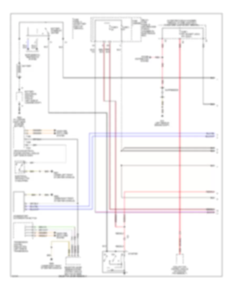
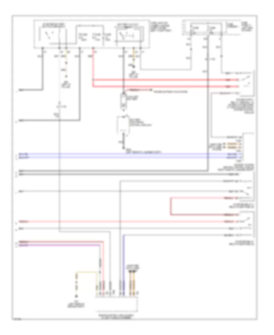
2.0L Turbo, Starting Wiring Diagram for Audi Q5 Premium 2014
List of elements for 2.0L Turbo, Starting Wiring Diagram for Audi Q5 Premium 2014:
- 2.0l turbo
- 3.0l sc
- 3.0l turbo diesel
- 3.0l turbo diesel & 3.0l sc 2.0l turbo
- Access/start authorization button
- Battery
- Battery interrupt igniter
- Battery jump start terminal (terminal 30 wire junction 2) (in center plenum chamber)
- Battery monitoring control module (left side of luggage compt)
- Charging circuit
- Comfort system central control module (right side of luggage compt)
- Computer data lines system
- Engine control module (ecm) (except diesel: in left plenum chamber) (diesel: left rear of engine)
- Engine controls system
- Fuse 3 5a
- Fuse 9 5a
- Fuse carrier 1
- Fuse panel a (on battery positive terminal)
- G624 (in luggage compt near starter battery)
- G668
- G688 (under right front of center console)
- G887 (w/ navigation) g688 (w/o navigation) (w/o navigation: under right front of center console)
- Ignition/ starter switch
- Navigation
- Nca
- Relay/fuse panel b (driver's side plenum chamber on electronics box)
- Selector lever sensor system control module (bottom of gear selector lever assembly)
- Start/stop mode button
- Starter
- Starter relay (relay/fuse panel b)
- Starter relay 2 (relay/fuse panel b)
- Steering column electronic systems control module (on steering column)
- T16b
- T16f
- T17c
- T17q
- T32a
- T32b
- T32c
- T32e
- T5i
- T91
- T94
- Transmission control module (tcm) (left side of transmission)
- Vehicle electrical system control module (left side of dash)
- Voltage stabilizer (w/ start/stop system) (right side of luggage compt)
- W/ start/stop system
- W/o
- W/o start/stop system
2.0L TURBO HYBRID
2.0L Turbo Hybrid, Charging Wiring Diagram for Audi Q5 Premium 2014
List of elements for 2.0L Turbo Hybrid, Charging Wiring Diagram for Audi Q5 Premium 2014:
- (left side of luggage compt) battery monitoring control module
- 2.0l turbo
- 3.0l sc & 3.0l turbo diesel
- 3.0l turbo diesel & 3.0l sc
- Battery
- Battery interrupt igniter
- Battery jump start terminal (terminal 30 wire junction 2) (in center plenum chamber)
- Computer data lines system
- Data bus on board diagnostic interface (right center of dash)
- Fuse panel a (on battery positive terminal)
- G624 (in luggage compt near starter battery)
- Generator & voltage regulator
- Instrument cluster control module
- Starter
- T17e
- T17r
- T5l
- Voltage stabilizer (w/ start/stop system) (right side of luggage compt)
2.0L Turbo Hybrid, Starting Wiring Diagram (1 of 2) for Audi Q5 Premium 2014
List of elements for 2.0L Turbo Hybrid, Starting Wiring Diagram (1 of 2) for Audi Q5 Premium 2014:
- (400w)
- (except 400w)
- (in center plenum chamber) terminal 30 wire junction 2 w/ battery jump start terminal
- 15a
- Access/start authorization button
- Battery
- Battery interrupt igniter
- Battery monitoring control module (left side of luggage compt)
- Computer data lines system
- Coolant fan control module (on cooling fan assembly)
- Electrical drive button (if equipped)
- Fuse 1 60a 40a
- Fuse 3 5a
- Fuse 9 5a
- Fuse carrier
- Fuse panel a (on battery positive terminal)
- G12 (left rear of engine compt)
- G624 (in luggage compt near starter battery)
- G687 (under left front of center console)
- G688 (under right front of center console)
- G688 under right front of center console)
- Nca
- Power distribution system
- Red
- Relay/ fuse panel b (driver's side plenum chamber on electronics box)
- Selector lever sensor system control module (bottom of gear selector lever assembly)
- Starter
- Suppressor
- T16b
- T17q
- T32a
- T32b
- T5i
- Transmission control module (tcm) (left side of transmission)
- Vehicle electrical system control module (left side of dash)
2.0L Turbo Hybrid, Starting Wiring Diagram (2 of 2) for Audi Q5 Premium 2014
List of elements for 2.0L Turbo Hybrid, Starting Wiring Diagram (2 of 2) for Audi Q5 Premium 2014:
- 16a
- Auxiliary battery
- Battery cut-out relay
- Battery monitoring control module 2
- Comfort system central control module (right side of luggage compt)
- Computer data lines system
- Engine control module (ecm) (in left plenum chamber)
- Fuse 110a
- Fuse 125a
- Fuse 200a
- Fuse 40a
- Fuse 5a
- Fuse carrier 1
- Fuse panel c (left end of dash)
- G12 (left rear of engine compt)
- G50 (left "d" pillar)
- G676 (left rear of luggage compt)
- Nca
- Power distribution system
- Red
- Starter battery switch-over relay
- Starter relay (relay/fuse panel b)
- Starter relay 2 (relay/fuse panel b)
- T105
- T17r
- T32c
- T32d
- T32e
- T91
- Wire junction (under luggage compt cover, next to battery)
3.0L SC
3.0L SC, Charging Wiring Diagram for Audi Q5 Premium 2014
List of elements for 3.0L SC, Charging Wiring Diagram for Audi Q5 Premium 2014:
- (left side of luggage compt) battery monitoring control module
- 2.0l turbo
- 3.0l sc & 3.0l turbo diesel
- 3.0l turbo diesel & 3.0l sc
- Battery
- Battery interrupt igniter
- Battery jump start terminal (terminal 30 wire junction 2) (in center plenum chamber)
- Computer data lines system
- Data bus on board diagnostic interface (right center of dash)
- Fuse panel a (on battery positive terminal)
- G624 (in luggage compt near starter battery)
- Generator & voltage regulator
- Instrument cluster control module
- Starter
- T17e
- T17r
- T5l
- Voltage stabilizer (w/ start/stop system) (right side of luggage compt)
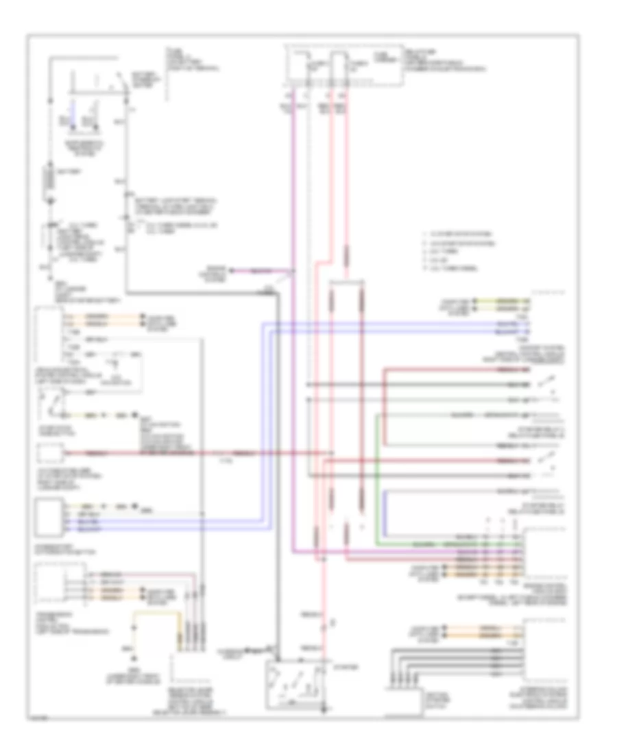
3.0L SC, Starting Wiring Diagram for Audi Q5 Premium 2014
List of elements for 3.0L SC, Starting Wiring Diagram for Audi Q5 Premium 2014:
- 2.0l turbo
- 3.0l sc
- 3.0l turbo diesel
- 3.0l turbo diesel & 3.0l sc 2.0l turbo
- Access/start authorization button
- Battery
- Battery interrupt igniter
- Battery jump start terminal (terminal 30 wire junction 2) (in center plenum chamber)
- Battery monitoring control module (left side of luggage compt)
- Charging circuit
- Comfort system central control module (right side of luggage compt)
- Computer data lines system
- Engine control module (ecm) (except diesel: in left plenum chamber) (diesel: left rear of engine)
- Engine controls system
- Fuse 3 5a
- Fuse 9 5a
- Fuse carrier 1
- Fuse panel a (on battery positive terminal)
- G624 (in luggage compt near starter battery)
- G668
- G688 (under right front of center console)
- G887 (w/ navigation) g688 (w/o navigation) (w/o navigation: under right front of center console)
- Ignition/ starter switch
- Navigation
- Nca
- Relay/fuse panel b (driver's side plenum chamber on electronics box)
- Selector lever sensor system control module (bottom of gear selector lever assembly)
- Start/stop mode button
- Starter
- Starter relay (relay/fuse panel b)
- Starter relay 2 (relay/fuse panel b)
- Steering column electronic systems control module (on steering column)
- T16b
- T16f
- T17c
- T17q
- T32a
- T32b
- T32c
- T32e
- T5i
- T91
- T94
- Transmission control module (tcm) (left side of transmission)
- Vehicle electrical system control module (left side of dash)
- Voltage stabilizer (w/ start/stop system) (right side of luggage compt)
- W/ start/stop system
- W/o
- W/o start/stop system
3.0L TURBO DIESEL
3.0L Turbo Diesel, Charging Wiring Diagram for Audi Q5 Premium 2014
List of elements for 3.0L Turbo Diesel, Charging Wiring Diagram for Audi Q5 Premium 2014:
- (left side of luggage compt) battery monitoring control module
- 2.0l turbo
- 3.0l sc & 3.0l turbo diesel
- 3.0l turbo diesel & 3.0l sc
- Battery
- Battery interrupt igniter
- Battery jump start terminal (terminal 30 wire junction 2) (in center plenum chamber)
- Computer data lines system
- Data bus on board diagnostic interface (right center of dash)
- Fuse panel a (on battery positive terminal)
- G624 (in luggage compt near starter battery)
- Generator & voltage regulator
- Instrument cluster control module
- Starter
- T17e
- T17r
- T5l
- Voltage stabilizer (w/ start/stop system) (right side of luggage compt)
3.0L Turbo Diesel, Starting Wiring Diagram for Audi Q5 Premium 2014
List of elements for 3.0L Turbo Diesel, Starting Wiring Diagram for Audi Q5 Premium 2014:
- 2.0l turbo
- 3.0l sc
- 3.0l turbo diesel
- 3.0l turbo diesel & 3.0l sc 2.0l turbo
- Access/start authorization button
- Battery
- Battery interrupt igniter
- Battery jump start terminal (terminal 30 wire junction 2) (in center plenum chamber)
- Battery monitoring control module (left side of luggage compt)
- Charging circuit
- Comfort system central control module (right side of luggage compt)
- Computer data lines system
- Engine control module (ecm) (except diesel: in left plenum chamber) (diesel: left rear of engine)
- Engine controls system
- Fuse 3 5a
- Fuse 9 5a
- Fuse carrier 1
- Fuse panel a (on battery positive terminal)
- G624 (in luggage compt near starter battery)
- G668
- G688 (under right front of center console)
- G887 (w/ navigation) g688 (w/o navigation) (w/o navigation: under right front of center console)
- Ignition/ starter switch
- Navigation
- Nca
- Relay/fuse panel b (driver's side plenum chamber on electronics box)
- Selector lever sensor system control module (bottom of gear selector lever assembly)
- Start/stop mode button
- Starter
- Starter relay (relay/fuse panel b)
- Starter relay 2 (relay/fuse panel b)
- Steering column electronic systems control module (on steering column)
- T16b
- T16f
- T17c
- T17q
- T32a
- T32b
- T32c
- T32e
- T5i
- T91
- T94
- Transmission control module (tcm) (left side of transmission)
- Vehicle electrical system control module (left side of dash)
- Voltage stabilizer (w/ start/stop system) (right side of luggage compt)
- W/ start/stop system
- W/o
- W/o start/stop system