AUTOMOTIVE ELECTRICIANS PORTAL

STARTING/CHARGING – Buick Allure CXL 2009 – SYSTEM WIRING DIAGRAMS

STARTING/CHARGING

Charging Wiring Diagram for Buick Allure CXL 2009

Charging Wiring Diagram for Buick Allure CXL 2009 https://portal-diagnostov.com/license.html
https://portal-diagnostov.com/license.html Automotive Electricians Portal FZCO Automotive Electricians Portal FZCO
Download PDF file

List of elements for Charging Wiring Diagram for Buick Allure CXL 2009:
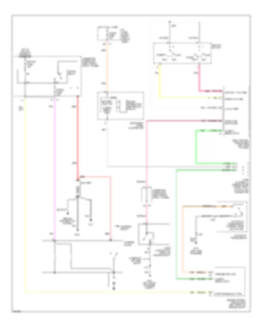
  • (in i/p wiring harness, 21 cm from lamp assembly switch)
  • (not used) a
  • 10 volt ref
  • 3.8l
  • 5.3l
  • Batt +
  • Battery
  • Battery current sensor (near battery)
  • Body control module (bcm) (left side of dash)
  • Charge indicator
  • Clstr fuse 10a
  • Computer data lines system
  • Current sensor low ref
  • Current sensor sig
  • Driver information center (dic) display
  • Ecm class 2 serial data
  • Engine control module (ecm) (left front of engine compt)
  • G102 (3.8l: near battery)
  • G111 (3.8l: lower left rear of engine)
  • G202 (left side of dash)
  • Generator
  • Generator field duty cycle sig
  • Generator turn on sig
  • Gnd
  • Ground
  • Hot at all times
  • I/p class 2 serial data
  • I/p fuse block (right side of dash)
  • Instrument panel cluster (ipc)
  • Interior lights system
  • J204
  • J211
  • Jx205 (clipped to knee bolster panel, right of data link connector)
  • Logic
  • Pcm class 2 serial data
  • Power distribution system
  • Powertrain control module (pcm)
  • Red
  • Remote st sensor sig
  • Starter motor

3.8L VIN 2

3.8L VIN 2, Starting Wiring Diagram for Buick Allure CXL 2009

3.8L VIN 2, Starting Wiring Diagram for Buick Allure CXL 2009 https://portal-diagnostov.com/license.html
https://portal-diagnostov.com/license.html Automotive Electricians Portal FZCO Automotive Electricians Portal FZCO
Get access to all wiring diagrams of the carDownload PDF file

List of elements for 3.8L VIN 2, Starting Wiring Diagram for Buick Allure CXL 2009:
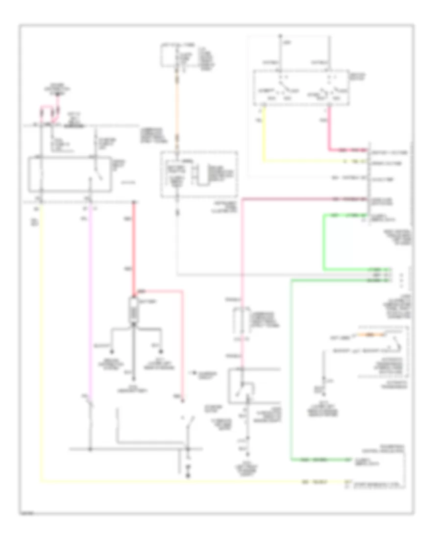
  • (not used)
  • 12-volt ref
  • Acc
  • Automatic transmission
  • Automatic transmission internal mode
  • Battery
  • Battery positive
  • Body control module (bcm) (left side of dash)
  • C11
  • C12
  • Charging circuit
  • Class 2 serial data
  • Clstr fuse 10a
  • Crank relay
  • Crank voltage
  • Driver information center (dic) display
  • G101 (left front of engine compt)
  • G102 (near battery)
  • G111 (lower left rear of engine)
  • G113 (lower left rear of engine, near starter)
  • Ground distribution system
  • Hood ajar switch (front of engine compt)
  • Hood ajar switch sig
  • Hot at all times
  • Hot w/ ign 1 relay energized
  • I/p fuse block (right side of dash)
  • Ignition 1 voltage
  • Ignition switch
  • Instrument panel cluster (ipc)
  • J101
  • J112
  • J200
  • Jx205 (clipped to knee bolster panel, right of data link connector)
  • Lock
  • Logic
  • Pcm fuse 15 10a
  • Pnk
  • Power distribution system
  • Powertrain control module (pcm)
  • Red
  • Run
  • Start
  • Start enable rly ctrl
  • Starter fuse 33 40a
  • Starter motor
  • Switch (ims)
  • Underhood fuse block (right front strut tower)
  • W/ remote keyless entry

5.3L VIN C

5.3L VIN C, Starting Wiring Diagram for Buick Allure CXL 2009

5.3L VIN C, Starting Wiring Diagram for Buick Allure CXL 2009 https://portal-diagnostov.com/license.html
https://portal-diagnostov.com/license.html Automotive Electricians Portal FZCO Automotive Electricians Portal FZCO
Get access to all wiring diagrams of the carDownload PDF file

List of elements for 5.3L VIN C, Starting Wiring Diagram for Buick Allure CXL 2009:

  • 12-volt ref
  • Acc
  • Automatic transmission
  • Automatic transmission internal mode
  • Battery
  • Battery positive
  • Body control module (bcm) (left side of dash)
  • Charging circuit
  • Class 2 serial data
  • Clstr fuse 10a
  • Crank voltage
  • Driver information center (dic) display
  • Ecm ign fuse 10a
  • Engine control module (ecm) (left front of engine compt)
  • G101 (left front of engine compt)
  • G102
  • G111
  • G115 (left side of engine)
  • Ground distribution system
  • Hood ajar switch (front of engine compt)
  • Hood ajar switch sig
  • Hot at all times
  • Hot w/ ign main pcb relay energized
  • I/p fuse block (right side of dash)
  • Ignition 1 voltage
  • Ignition switch
  • Instrument panel cluster (ipc)
  • J112
  • J125
  • J200
  • Jx205 (clipped to knee bolster panel, right of data link connector)
  • Lock
  • Logic
  • Park/neutral sig
  • Pnk
  • Red
  • Run
  • Start
  • Start enable rly ctrl
  • Starter motor
  • Strtr fuse 40a
  • Strtr relay
  • Switch (ims)
  • Underhood fuse block (right front strut tower)
  • W/ remote keyless entry
  • X100