STARTING/CHARGING
Charging Wiring Diagram for Buick Roadmaster Estate Wagon 1995

List of elements for Charging Wiring Diagram for Buick Roadmaster Estate Wagon 1995:
- a9, b11
- b6, a10
- (not used)
- (solid state)
- *buick **chevy
- Ac sense
- Bat
- Battery
- C 1995 vftc
- Check gage ind.
- Dc sense
- Field (rotor)
- G101 (right front fender, near battery)
- G119 (front of right cylinder head)
- Generator (right side of engine, forward of right valve cover)
- Hot in run
- Hot in run or start
- I/p fuse block
- I/p indc fuse 11 10a
- Input
- Instrument cluster
- Pnk
- Power distribution
- Rectifier bridge
- Regulator
- Sec fan fuse 8 10a
- Starter solenoid
- Stator
- Turn on
- Turn on input
- Underhood electrical center
- Volts ind.
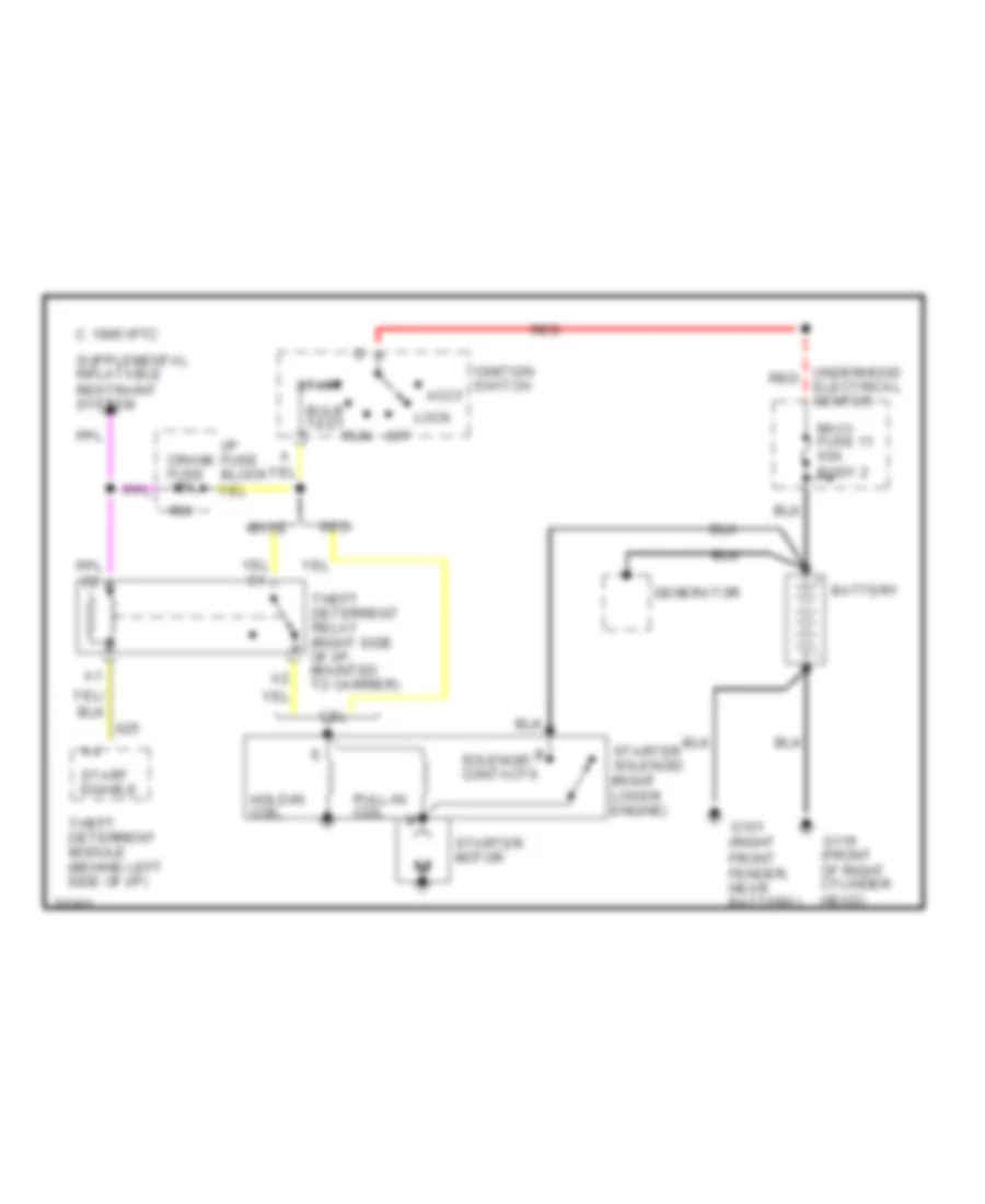
Starting Wiring Diagram for Buick Roadmaster Estate Wagon 1995
List of elements for Starting Wiring Diagram for Buick Roadmaster Estate Wagon 1995:
- #24
- Accy
- Base
- Battery
- Bulb test
- C 1995 vftc
- Crank fuse 10a
- Electrical center
- G101 (right front fender, near battery)
- G119 (front of right cylinder head)
- Generator
- Hold-in coil
- I/p fuse block
- Ignition switch
- Lock
- Maxi- fuse 11 60a body 2
- Off
- Pull-in coil
- Red
- Run
- Seo
- Solenoid contacts
- Start
- Start enable
- Starter motor
- Starter solenoid (right lower engine)
- Theft deterrent module (behind left side of i/p)
- Theft deterrent relay (right side of i/p, mounted to carrier)
- Underhood red