STARTING/CHARGING
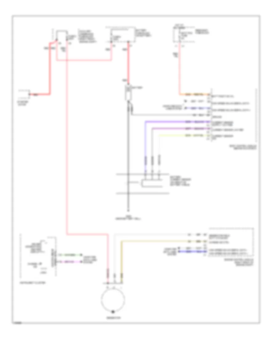
Charging Wiring Diagram, with Stop/Start System for Cadillac ATS 2013

List of elements for Charging Wiring Diagram, with Stop/Start System for Cadillac ATS 2013:
Charging Wiring Diagram, without Stop/Start System for Cadillac ATS 2013
List of elements for Charging Wiring Diagram, without Stop/Start System for Cadillac ATS 2013:
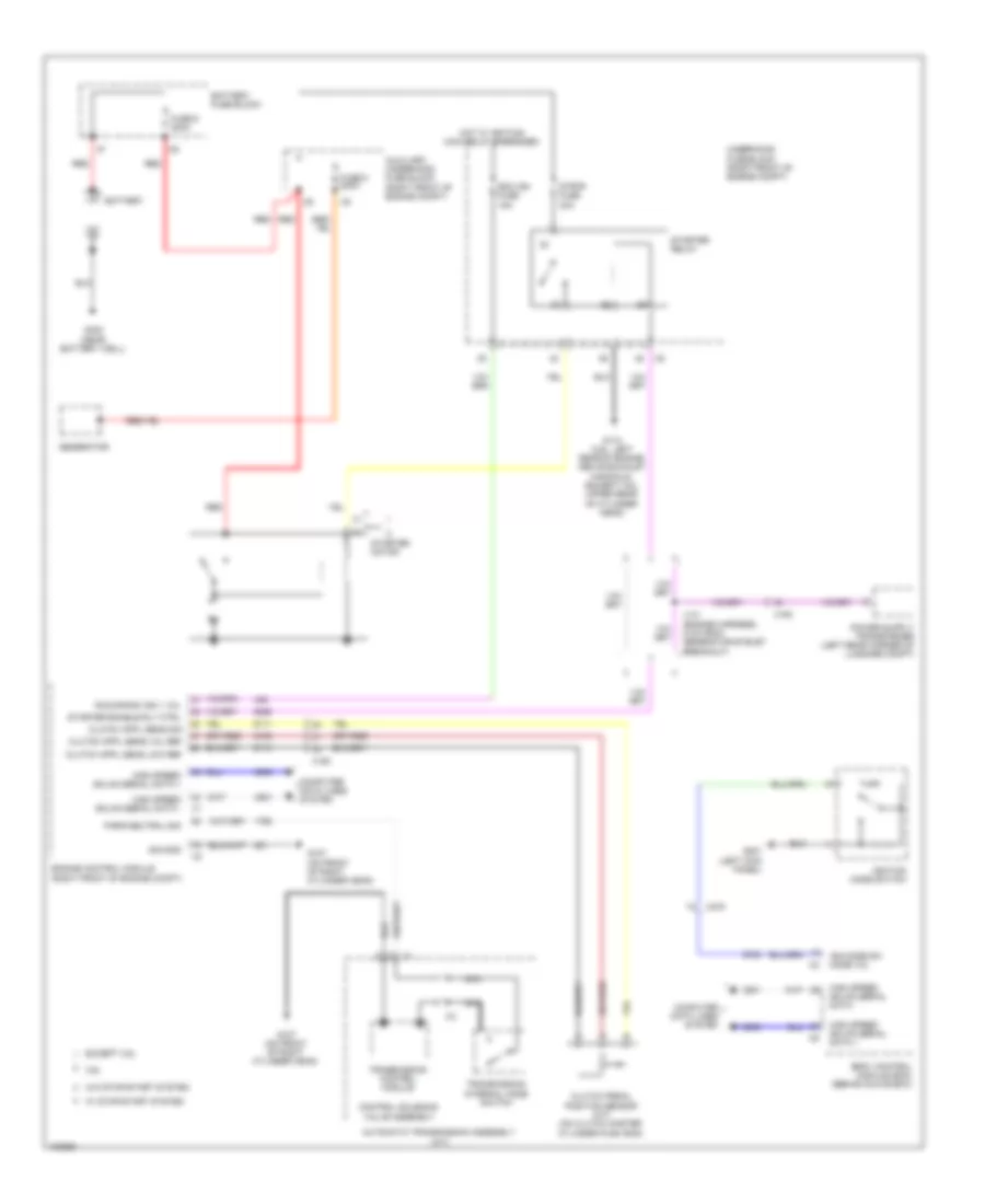
Starting Wiring Diagram for Cadillac ATS 2013
List of elements for Starting Wiring Diagram for Cadillac ATS 2013: