STARTING/CHARGING
Charging Wiring Diagram for Cadillac XLR V 2006

List of elements for Charging Wiring Diagram for Cadillac XLR V 2006:
- (not used) a
- 4.4l 4.6l
- A2 c2
- A5 c1
- Battery
- Battery saver active charge system fault high voltage low voltage service elect system
- Check gages
- Class 2 (bcm)
- Computer data lines system
- Ecm high speed gmlan serial data bus +
- Ecm high speed gmlan serial data bus -
- Engine control module (ecm) (behind lower right front fender)
- G104 (right side of engine compt, under battery)
- G106
- Generator
- Generator field duty cycle signal
- Generator turn on signal
- Head up display (hud)
- Horn fuse 2 15a
- Hud class 2 serial data
- Ign
- Instrument panel cluster (ipc)
- Ipc class 2 serial data
- Logic
- Message center
- Message request
- Message request (bcm)
- Red
- Splice pack sp106 (in engine harness, right rear of engine compartment by battery, grounded to g106)
- Starter
- Tan
- Underhood fuse block (right rear of engine compt)
- Volts
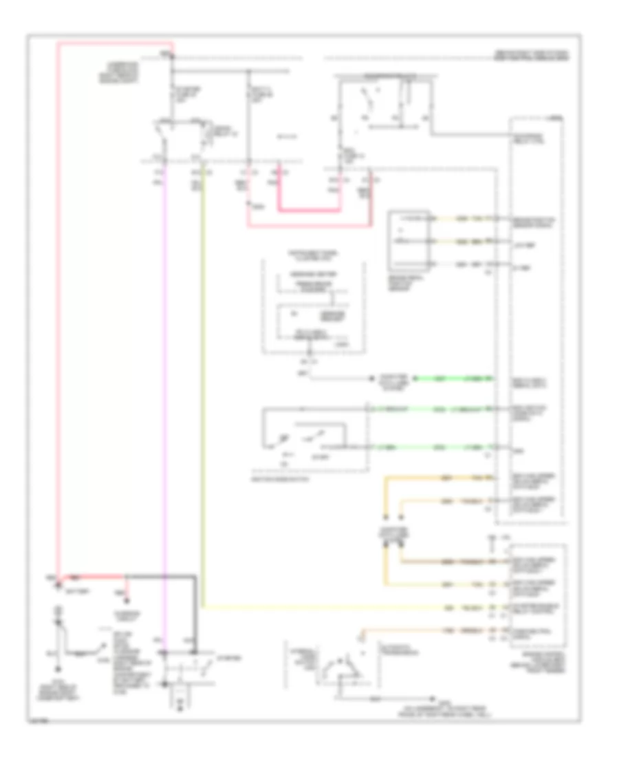
Starting Wiring Diagram for Cadillac XLR V 2006
List of elements for Starting Wiring Diagram for Cadillac XLR V 2006:
- (behind right side of dash) body control module (bcm)
- 4.4l
- 4.6l
- 5v ref
- A13
- A14
- A5 c1
- A9 c3
- Automatic transmission
- B10 c4
- Batt 3 fuse 26 60a
- Battery
- Bcm class 2 serial data
- Bcm high speed gmlan serial data bus +
- Bcm high speed gmlan serial data bus -
- Bcm ignition mode data signal
- Brake pedal position sensor
- Brake position sensor signal
- C1 c4
- C13
- C14
- C2 e12
- C3 d1
- Charging circuit
- Computer data lines system
- Crank relay 43
- Ecm fuse 12 15a
- Ecm high speed gmlan serial data bus +
- Ecm high speed gmlan serial data bus -
- Engine control module (ecm) (behind lower right front fender)
- F12
- G104 (right side of engine compt, under battery)
- G106
- G402 (on underbody, on right rear frame, by right rear wheel well)
- Gnd
- Ignition mode switch
- Instrument panel cluster (ipc)
- Internal mode switch (ims)
- Ipc class 2 serial data
- Logic
- Low ref
- Message center
- Message request
- Nca
- Off
- Park/neutral signal
- Pnk
- Press brake to start
- Red
- Run/crank relay 2
- Run/crank relay ctrl
- S208
- Splice pack sp106 (in engine harness, right rear of engine compartment by battery, grounded to g106)
- Start
- Starter
- Starter enable relay control
- Starter fuse 30 40a
- Tan
- Underhood fuse block (right rear of engine compt)