STARTING/CHARGING
Charging Wiring Diagram for Chevrolet Corvette 2005

List of elements for Charging Wiring Diagram for Chevrolet Corvette 2005:
- (not used) a
- Battery
- Battery saver active
- Body control module (bcm) (right footwell, on toe board)
- Body control module (pcm) (mounted on toe board, in right footwell)
- Charge system fault
- Class 2 serial data
- Cluster fuse 8 10a
- Computer
- Computer data lines
- D10
- Data lines
- G104 (on right frame rail, below battery tray)
- G106 (on right side of engine, above starter)
- G201 (base of left "a" pillar)
- Generator
- Generator f terminal
- Generator l terminal
- Ground
- Hi speed gmlan serial data +
- Hi speed gmlan serial data -
- High voltage
- Horn/ alt sense fuse 2 15a
- Hot at all times
- Ign 1 volt
- Instrument panel cluster
- Ipc class 2 serial data
- Logic
- Low voltage
- Massage center
- Power distribution system
- Powertrain control module (pcm) or engine control module (ecm) (behind right front fender, between wheelhouse & dash panel)
- Red
- S201
- Service elect system
- Splice pack sp205 (in i/p harn, by park brake assembly)
- Splice pack sp208 (in i/p harn, (below inflatable restraint module)
- Starter
- System
- Tan
- Underhood fuse block (right side of eng compt)
- Volts
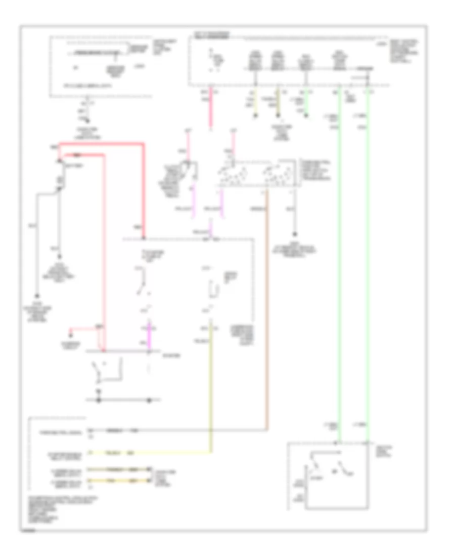
Starting Wiring Diagram for Chevrolet Corvette 2005
List of elements for Starting Wiring Diagram for Chevrolet Corvette 2005:
- (not used)
- A/t
- A13
- A14
- B10
- Battery
- Bcm class 2 serial data
- Bcm ignition mode data signal
- Body control module (pcm) (mounted on toe board, in right footwell)
- C13
- C14
- C2 f12
- Charging circuit
- Clutch pedal start switch (on board, beneath clutch pedal)
- Computer data lines system
- Crank relay
- E12
- Ecm fuse 15a
- G104 (on right frame rail, below battery tray)
- G106 (on right side of engine, above starter)
- G402 (at rear of vehicle, on inner side of right frame rail)
- Ground
- Hi speed gmlan serial data +
- Hi speed gmlan serial data -
- High speed gmlan serial data +
- High speed gmlan serial data -
- Hot w/ run/crank relay energized
- Ignition mode switch
- Instrument panel cluster (ipc)
- Ipc class 2 serial data
- Logic
- M/t
- Message center
- Message request (bcm)
- Off
- Ohms
- Park/neutral position (pnp) switch (on top of transmission)
- Park/neutral signal
- Pnk
- Powertrain control module (pcm) or engine control module (ecm) (behind right front fender, between wheelhouse & dash panel)
- Press brake to start
- Red
- Start
- Starter
- Starter enable relay control
- Starter fuse 30 40a
- Tan
- Underhood fuse block (right side of eng compt)