STARTING/CHARGING
Charging Wiring Diagram for Chevrolet Impala 2001

List of elements for Charging Wiring Diagram for Chevrolet Impala 2001:
- (2000 only)
- (not used)
- A/c rly (cmpr) fuse 10a
- Battery
- Charge warning indicator (red)
- Class 2 serial data
- Computer data lines
- F terminal monitor
- Fusible link (10 ga- rust)
- G114 (lower left rear of engine, on transaxle stud)
- G118 (right side of engine compartment, on frame rail)
- Generator
- Generator turn on signal
- Hot at all times
- Hot in acc, on or start
- Instrument cluster
- Left i/p junction block (end of dash in left door opening)
- Pcm/bcm/clstr fuse 10a
- Power distribution system
- Powertrain control module (pcm) (in air cleaner box)
- Red
- Splice pack sp205 (next to left i/p accessory wiring junction block wiring harness, taped on harness)
- Starter solenoid
- Underhood junction block (top) (in right side of engine compartment, forward of strut tower)
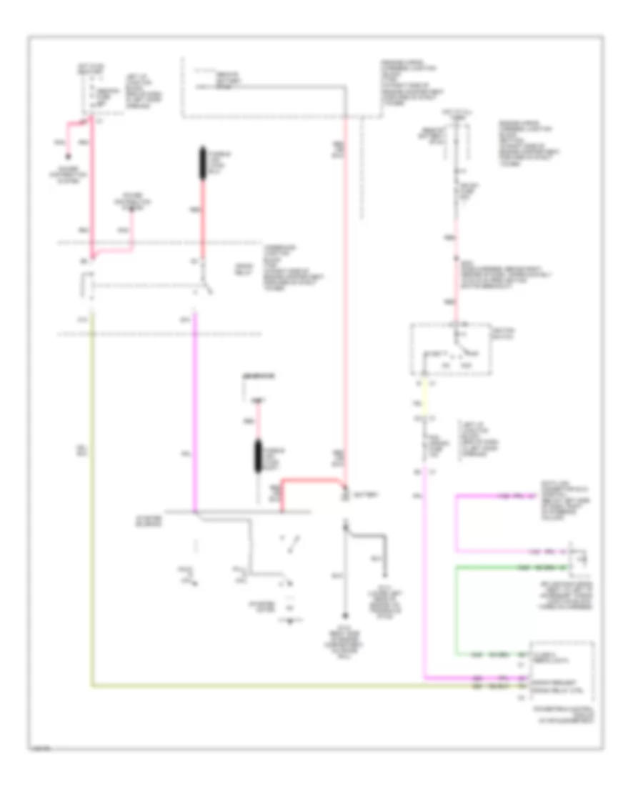
Starting Wiring Diagram for Chevrolet Impala 2001
List of elements for Starting Wiring Diagram for Chevrolet Impala 2001:
- Abs/pcm fuse 10a
- Acc
- B10
- Batt
- Battery
- C10
- Class 2 serial data
- Crank relay
- Crank relay ctrl
- Crank request
- Data link connector (dlc) (partial) (below left side of dash, right of steering column)
- Engine wiring harness junction block (bottom) (in right side of engine compartment, forward of strut tower)
- Engine wiring harness junction block (top) (in right side of engine compartment, forward of strut tower)
- Fusible link (10-ga rust)
- G114 (lower left rear of engine, on transaxle stud)
- G118 (right side of engine compartment, on frame rail)
- Generator
- Hold- in coil
- Hot at all times
- Hot in on or start
- Ign sw fuse 60a
- Ignition switch
- Left i/p junction block (end of dash, in left door opening)
- Off
- Pcm (crank) fuse 10a
- Pnk
- Power distribution system
- Powertrain control module (in air cleaner box)
- Pull- in coil
- Red
- Remote battery stud
- S234 (dash harness, behind right center of dash, approximately 15 cm (6 in) from ignition switch breakout)
- Splice pack sp205 (next to left i/p accessory wiring junction block, taped on harness)
- Start
- Starter motor
- Starter solenoid
- Underhood junction block (top) (in right side of engine compartment, forward of strut tower)