STARTING/CHARGING
Charging Wiring Diagram for Chevrolet Impala Limited LTZ 2014

List of elements for Charging Wiring Diagram for Chevrolet Impala Limited LTZ 2014:
- (on positive battery cable) battery current sensor
- 200a
- Batt +
- Battery
- Battery positive volt
- Body control module (bcm) (left side of dash)
- Charging indicator
- Computer data lines system
- Current sensor low ref
- Current sensor sig
- Display fuse 10a
- Driver information center (dic) display
- Engine control module (ecm) (inside air cleaner assembly)
- G102 (near battery)
- G113
- G202 (center of dash)
- Generator
- Generator field duty cycle sig
- Generator inline fuse
- Generator turn on sig
- Gnd
- Hi spd gmlan serial data bus +
- Hi spd gmlan serial data bus -
- High spd gmlan serial data bus +
- High spd gmlan serial data bus -
- Hot at all times
- Instrument panel cluster (ipc)
- Jx206 (i/p harness, near steering column)
- Lo spd gmlan serial data
- Logic
- Low ref
- Low spd gmlan serial data
- Pnk
- Power distribution system
- Red
- Rvc sen fuse 10a
- Starter
- Tan
- Underhood fuse block (right side of engine compt)
- X105
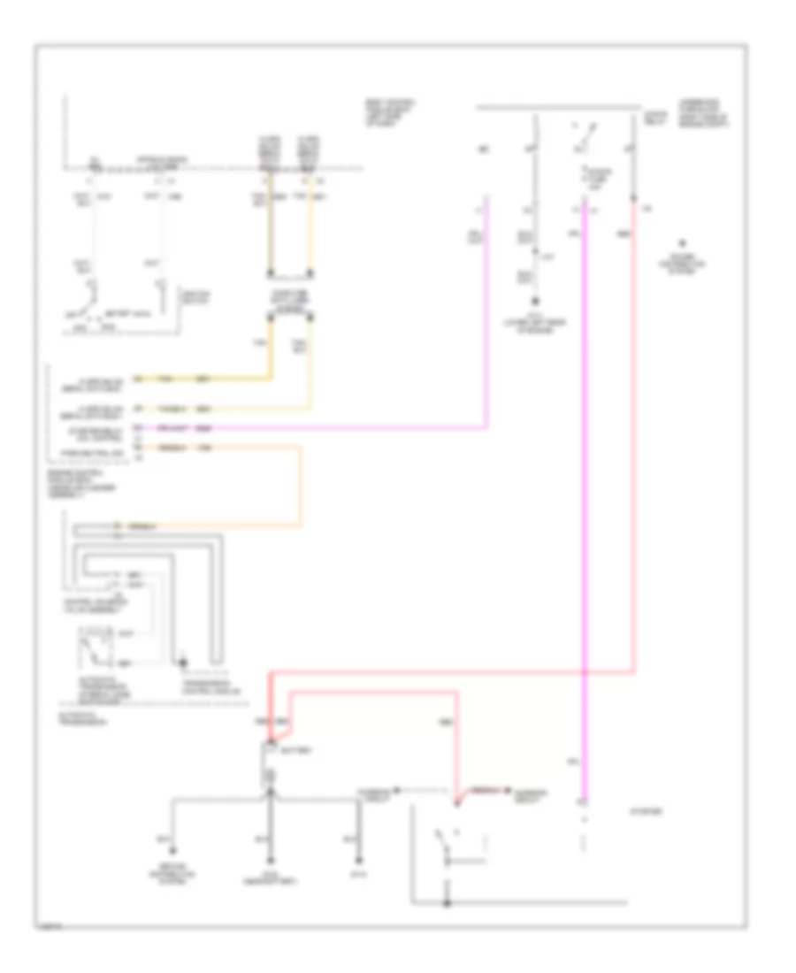
Starting Wiring Diagram for Chevrolet Impala Limited LTZ 2014
List of elements for Starting Wiring Diagram for Chevrolet Impala Limited LTZ 2014:
- 5v ref
- Acc
- Automatic transmission
- Automatic transmission internal mode switch (ims)
- Battery
- Body control module (bcm) (left side of dash)
- Charging circuit
- Computer data lines system
- Control solenoid valve assembly
- Engine control module (ecm) (inside air cleaner assembly)
- G102 (near battery)
- G111 (lower left rear of engine)
- G113
- Ground distribution system
- Hi spd gmlan serial data bus +
- Hi spd gmlan serial data bus -
- Ignition switch
- J101
- Off
- Off/run crank voltage
- Park/neutral sig
- Power distribution system
- Red
- Run
- Start
- Starter
- Starter relay coil control
- Strtr fuse 40a
- Strtr relay
- Tan
- Tan/
- Transmission control module
- Underhood fuse block (right side of engine compt)