STARTING/CHARGING
Charging Wiring Diagram for Chevrolet Malibu LS 2012

List of elements for Charging Wiring Diagram for Chevrolet Malibu LS 2012:
- (left side of engine compartment)
- 2.4l (vin b)
- 3.6l
- Batt
- Batt sense fuse 54 5a
- Battery
- Battery current sensor (under battery)
- Body control module (bcm) (under center console)
- Charge ind
- Cluster/ theft fuse 10a
- Computer data lines system
- Current sensor low ref
- Current sensor signal
- D12
- Data bus +
- Data bus -
- Engine control module (ecm) (left front of engine compt)
- Fusible link bu
- G104 (left front corner of engine compt)
- G105
- G109 (left front corner of engine compt)
- Generator
- Generator field duty cycle sig
- Generator turn on sig
- Gnd
- High speed gmlan serial data bus +
- High speed gmlan serial data bus -
- Hot at all times
- Ibcm 1 fuse 30a
- Ign
- Instrument panel cluster (ipc)
- Logic
- Low ref
- Pnk
- Power distribution system
- Red
- Sens sig
- Serial data
- Starter motor
- Tan
- Underhood fuse block
- Volt
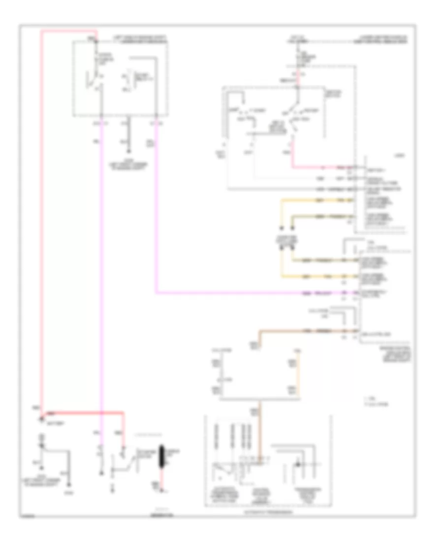
Starting Wiring Diagram for Chevrolet Malibu LS 2012
List of elements for Starting Wiring Diagram for Chevrolet Malibu LS 2012:
- (left side of engine compt)
- (under center console)
- 2.4l (vin b)
- 3.6l
- Acc
- Automatic transmission
- Automatic transmission internal mode switch (ims)
- Battery
- Body control module (bcm)
- C1 x2
- C10
- Computer data lines system
- Control solenoid valve assembly
- D1 x4
- D12 x1
- Engine control module (ecm) (left front of engine compt)
- Fusible link bu
- G104 (left front corner of engine compt)
- G105
- G109 (left front corner of engine compt)
- Generator
- High speed gmlan serial data bus +
- High speed gmlan serial data bus -
- Hot at all times
- Ign key resistor signal
- Ign lk ctrl sig
- Ign sensor fuse 2a
- Ignition 1
- Ignition switch
- Key in ignition switch
- Logic
- Off
- Off/run/ crank voltage
- Pnk
- Red
- Run
- Start
- Start relay 31
- Starter motor
- Starter rly coil ctrl
- Strtr fuse 26 30a
- Tan
- Transmission control module (tcm)
- Underhood fuse block
- X108 e