STARTING/CHARGING
Charging Wiring Diagram for Dodge Avenger 1997

List of elements for Charging Wiring Diagram for Dodge Avenger 1997:
- A-02
- A-03
- A-77
- A-78
- Acc
- Anti-lock brakes system
- Asd relay (left side of safety wall)
- B-41
- B-54
- Battery
- Brake
- C-04
- C-06
- Charge
- Combination meter
- Cruise con- trol system, defogger system, warning systems
- Dohc
- Engine compartment relay box
- Engine controls system
- Fuse 10a
- Fusible
- G100 (front of left front fender)
- G104 (rear of left front fender)
- G110 (left front of engine block)
- G116 (left side of safety wall)
- Generator
- Ignition switch
- J/c 3 (below engine compt rb)
- J/c 3 (below engine compt relay box)
- J/c 4 (below engine compt relay box)
- Junction block
- Link 1 120a
- Link 3 40a
- Link 5 30a
- Lock
- Powertrain control module (forward of left front strut tower)
- Red
- Sohc
- Start
- Starter motor
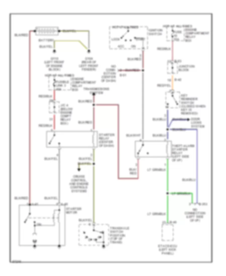
Starting Wiring Diagram, with A/T & Anti-theft for Dodge Avenger 1997
List of elements for Starting Wiring Diagram, with A/T & Anti-theft for Dodge Avenger 1997:
- A-40
- A-41
- Acc
- B-35x
- B-40
- B-42
- B-51
- B-63
- Battery
- Cruise control, and engine controls systems
- Door locks system
- Engine compartment relay box
- Etacs-ecu (left kick panel)
- Fuse 10a
- Fusible link 3 40a
- G104 (rear of left front fender)
- G110 (left front of engine block)
- Hot at all times
- Ignition switch
- J/c 4 (below engine compt relay box)
- Junction block
- Key reminder switch (closed when key is removed)
- Lock
- No conn- ection (center of dash)
- No connection (left side of i/p)
- Start
- Starter motor
- Starter relay (center of dash)
- Theft-alarm starter relay (left side of i/p)
- Transaxle switch position (top of trans)
- Transmissions system
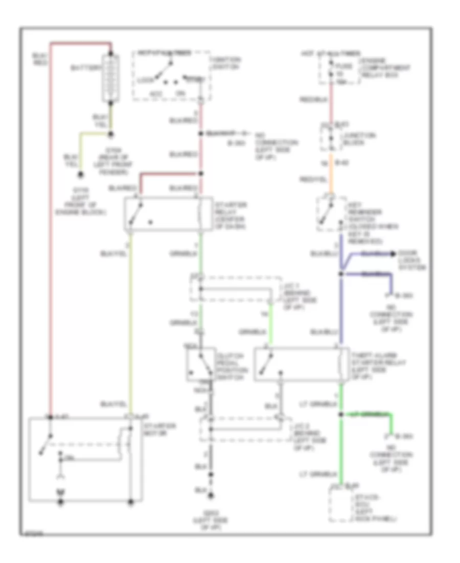
Starting Wiring Diagram, with M/T & Anti-theft for Dodge Avenger 1997
List of elements for Starting Wiring Diagram, with M/T & Anti-theft for Dodge Avenger 1997:
- A-40
- A-41
- Acc
- B-36x
- B-40
- B-42
- B-63
- Battery
- Clutch pedal position switch
- Door locks system
- Engine compartment relay box
- Etacs- ecu (left kick panel)
- Fuse 10a
- G104 (rear of left front fender)
- G110 (left front of engine block)
- G202 (left side of i/p)
- Hot at all times
- Ignition switch
- J/c 1 (behind left side of i/p)
- J/c 2 (behind left side of i/p)
- Junction block
- Key reminder switch (closed when key is removed)
- Lock
- Nca
- No connection (left side of i/p)
- Start
- Starter motor
- Starter relay (center of dash)
- Theft-alarm starter relay (left side of i/p)
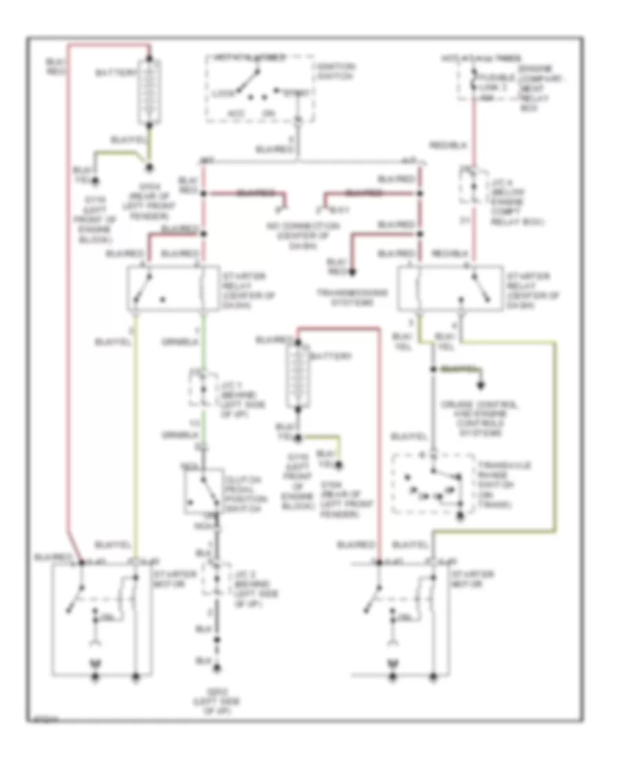
Starting Wiring Diagram, without Anti-theft for Dodge Avenger 1997
List of elements for Starting Wiring Diagram, without Anti-theft for Dodge Avenger 1997:
- A-40
- A-41
- A/t
- Acc
- B-51
- Battery
- Clutch pedal position switch
- Cruise control, and engine controls systems
- Engine compart- ment relay box
- Fusible link 3 40a
- G104 (rear of left front fender)
- G110 (left front of engine block)
- G202 (left side of i/p)
- Hot at all times
- Ignition switch
- J/c 1 (behind left side of i/p)
- J/c 2 (behind left side of i/p)
- J/c 4 (below engine compt relay box)
- Lock
- M/t
- Nca
- No connection (center of dash)
- Start
- Starter motor
- Starter relay (center of dash)
- Transaxle range switch (on trans)
- Transmissions systems