STARTING/CHARGING
Charging Wiring Diagram, without Dual Generators for Ford Econoline E250 1999

List of elements for Charging Wiring Diagram, without Dual Generators for Ford Econoline E250 1999:
- (engine compt harn, near starter motor relay) s1008
- (right front corner of engine compt) starter motor relay
- 0hms
- 6v (normal operation)
- 7.3l diesel
- Accy
- Auxiliary powertrain control connector (behind left side of dash)
- Battery junction box (left front of engine compt)
- C198
- C199
- C226
- Central junction box (left side of dash, near kick panel)
- Charge ind
- Engine compartment battery
- Fuse 5a
- Fuse 60a
- Fuse link c (18 ga- brown) (at starter motor relay)
- G120 (right side of engine)
- Generator/ regulator
- Ground distribution system
- Ignition switch
- In breakout to data link)
- Instrument cluster
- Lock
- Off
- Red
- Run
- S1009 (engine compt harn, near starter motor relay)
- S1010 (engine compt harn, near battery junction box)
- S1011 (engine compt harn, near battery junction box)
- S225 (engine compt harn, left rear of engine compt)
- Start
- Starting circuit
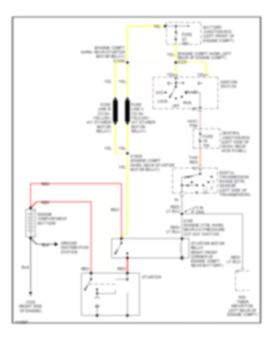
Starting Wiring Diagram for Ford Econoline E250 1999
List of elements for Starting Wiring Diagram for Ford Econoline E250 1999:
- (engine compt harn, near starter motor relay) s1008
- 5.4l cng
- Acc
- Battery junction box (left front of engine compt)
- Central junction box (left side of dash, near kick panel)
- Digital transmission range (dtr) sensor (left side of transmission)
- Engine compartment battery
- Fuse 10a
- Fuse 60a
- G120 (right side of engine)
- Ground distribution system
- Ignition switch
- Lock
- Motor relay)
- Ngv timer (near pcm, left rear of engine compt)
- Off
- Red
- Run
- Start
- Starter
- Starter motor relay (right front corner of engine compt, near battery)
- Tan/ red