STARTING/CHARGING
Charging Wiring Diagram for Honda CR-V LX 2010

List of elements for Charging Wiring Diagram for Honda CR-V LX 2010:
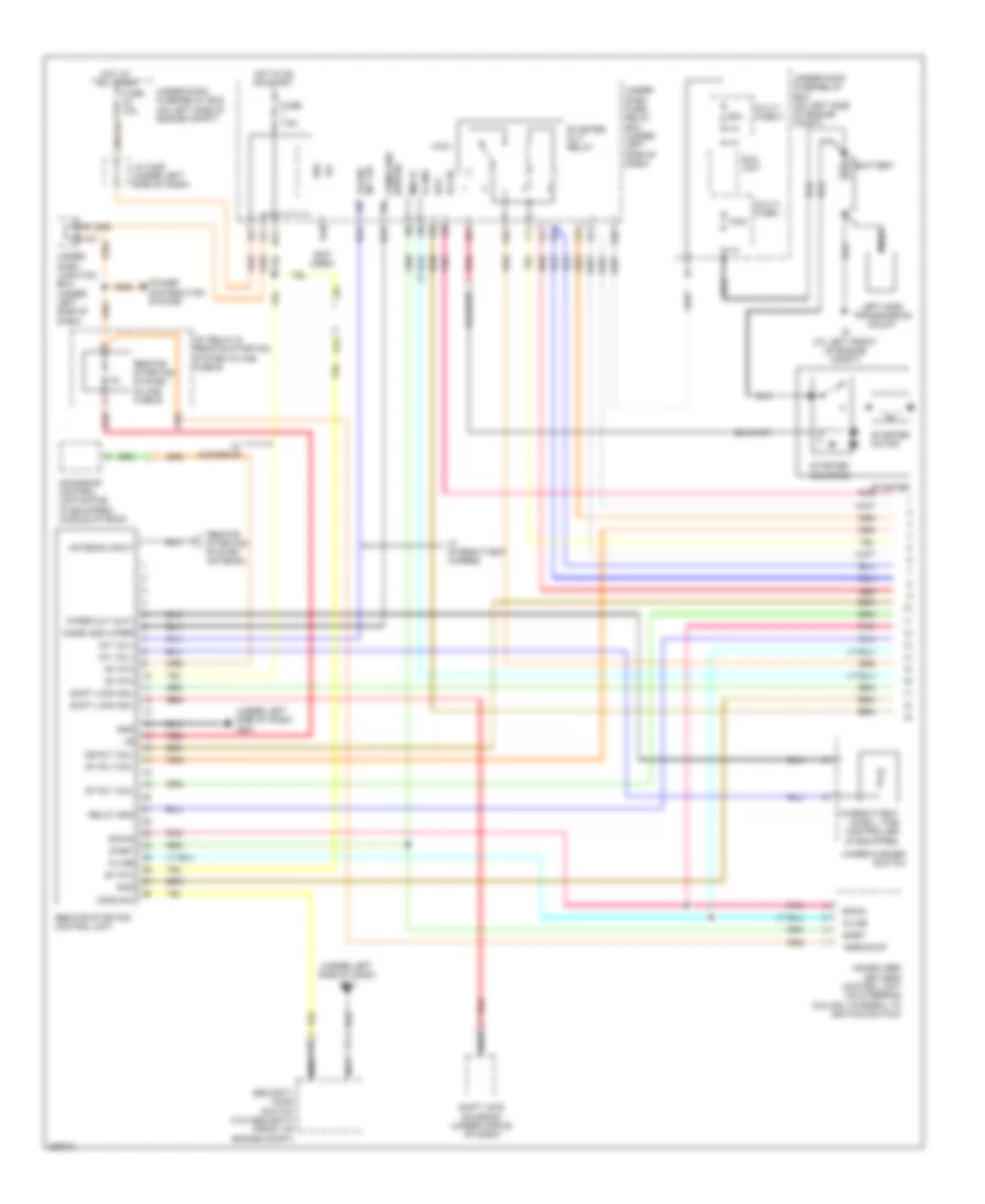
Remote Starting Wiring Diagram (1 of 2) for Honda CR-V LX 2010
List of elements for Remote Starting Wiring Diagram (1 of 2) for Honda CR-V LX 2010:
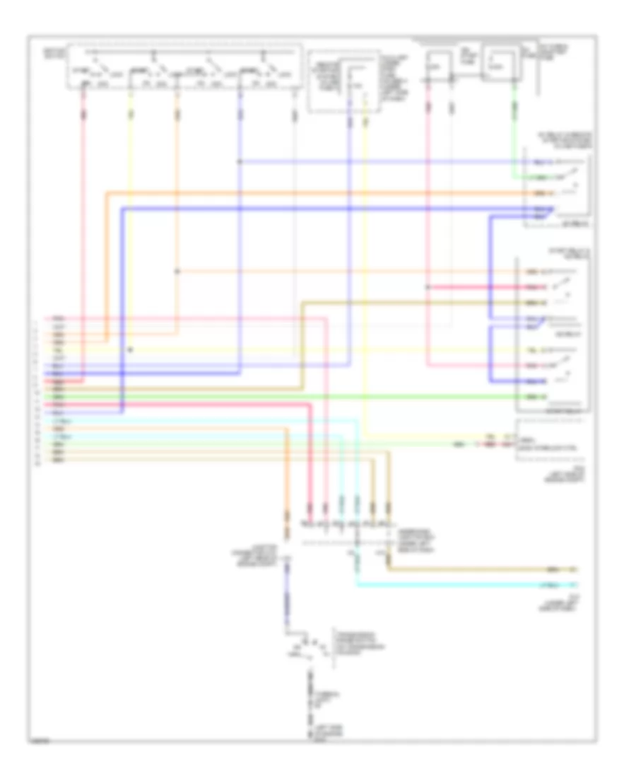
Remote Starting Wiring Diagram (2 of 2) for Honda CR-V LX 2010
List of elements for Remote Starting Wiring Diagram (2 of 2) for Honda CR-V LX 2010:
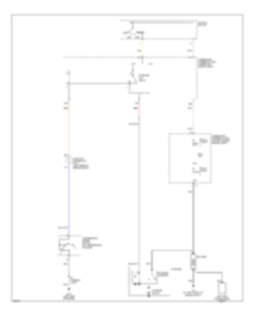
Starting Wiring Diagram for Honda CR-V LX 2010
List of elements for Starting Wiring Diagram for Honda CR-V LX 2010: