STARTING/CHARGING
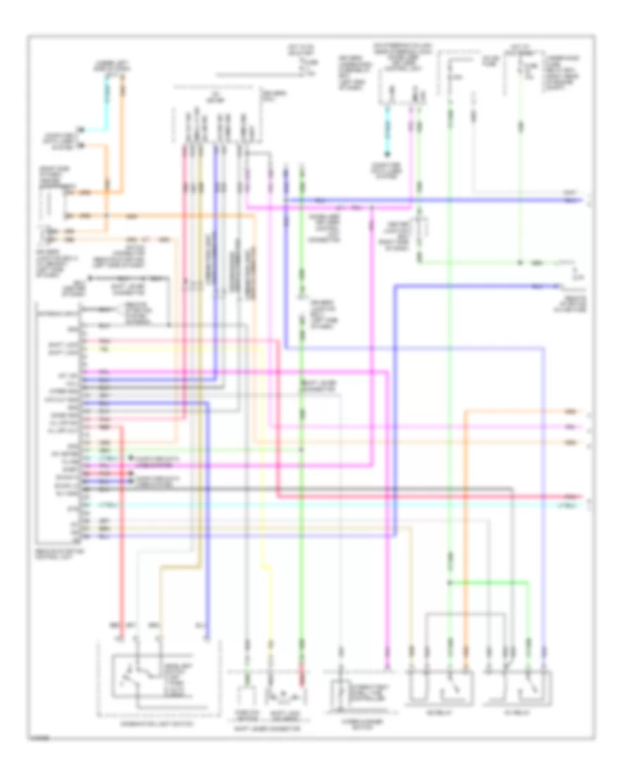
Charging Wiring Diagram for Honda Odyssey Touring 2013

List of elements for Charging Wiring Diagram for Honda Odyssey Touring 2013:
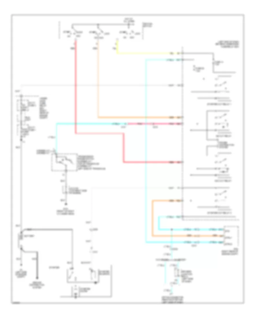
Remote Starting Wiring Diagram (1 of 2) for Honda Odyssey Touring 2013
List of elements for Remote Starting Wiring Diagram (1 of 2) for Honda Odyssey Touring 2013:
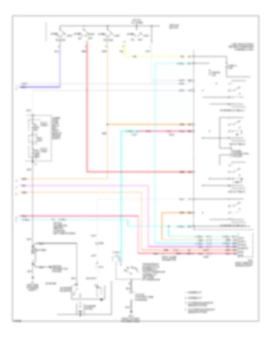
Remote Starting Wiring Diagram (2 of 2) for Honda Odyssey Touring 2013
List of elements for Remote Starting Wiring Diagram (2 of 2) for Honda Odyssey Touring 2013:
Starting Wiring Diagram for Honda Odyssey Touring 2013
List of elements for Starting Wiring Diagram for Honda Odyssey Touring 2013: