STARTING/CHARGING
Charging Wiring Diagram for Hyundai Elantra GL 1999

List of elements for Charging Wiring Diagram for Hyundai Elantra GL 1999:
- (gl)
- (gls)
- (in right front corner of engine compartment, behind battery) engine compartment relay & fuse box
- Battery
- Battery ground
- Charge indicator
- Dash fuse box (under left side of dash, at kick panel)
- E31-1
- E31-2
- Electronic time & alarm control module (etacm) (under center of dash, below radio)
- Engine controls system
- Engine running input
- Fuse 10 10a
- Fuse 9 10a
- Generator b
- Headlights system (drl control module) (if equipped)
- Hot in on or start
- I01-1
- I01-3
- I04-1
- I04-2
- Instrument cluster
- Pre- excitation resistor
- Red
- Starting system (start motor)
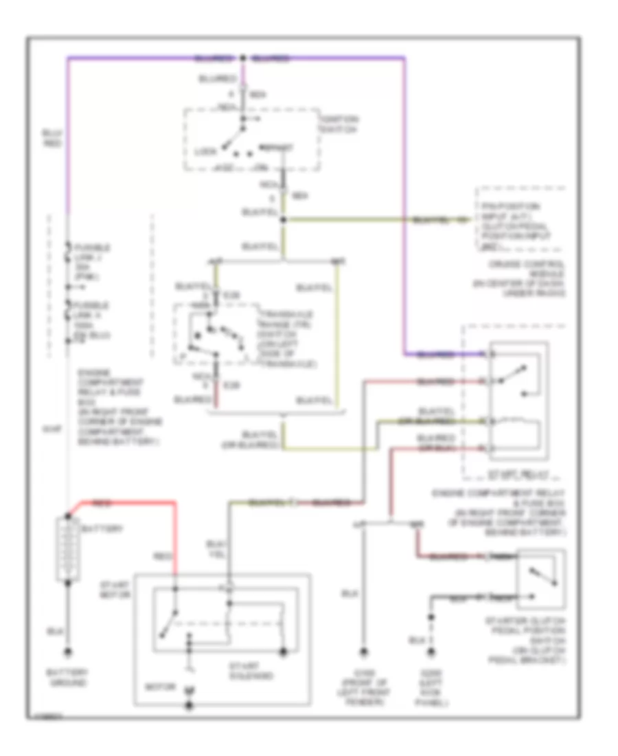
Starting Wiring Diagram for Hyundai Elantra GL 1999
List of elements for Starting Wiring Diagram for Hyundai Elantra GL 1999:
- A/t
- Acc
- Battery
- Battery ground
- Cruise control module (in center of dash, under radio)
- E28
- Engine compartment relay & fuse box (in right front corner of engine compartment, behind battery)
- Fusible link j 30a (pnk)
- G100 (front of left front fender)
- G200 (left kick panel)
- Ignition switch
- Lock
- M/t
- M24
- Motor
- N d
- Nca
- P/n position input (a/t) clutch pedal position input (m/t)
- Red
- Start
- Start motor
- Start relay
- Start solenoid
- Starter clutch pedal position switch (on clutch pedal bracket)
- Transaxle range (tr) switch (on left side of transaxle)