STARTING/CHARGING
2.0L TURBO
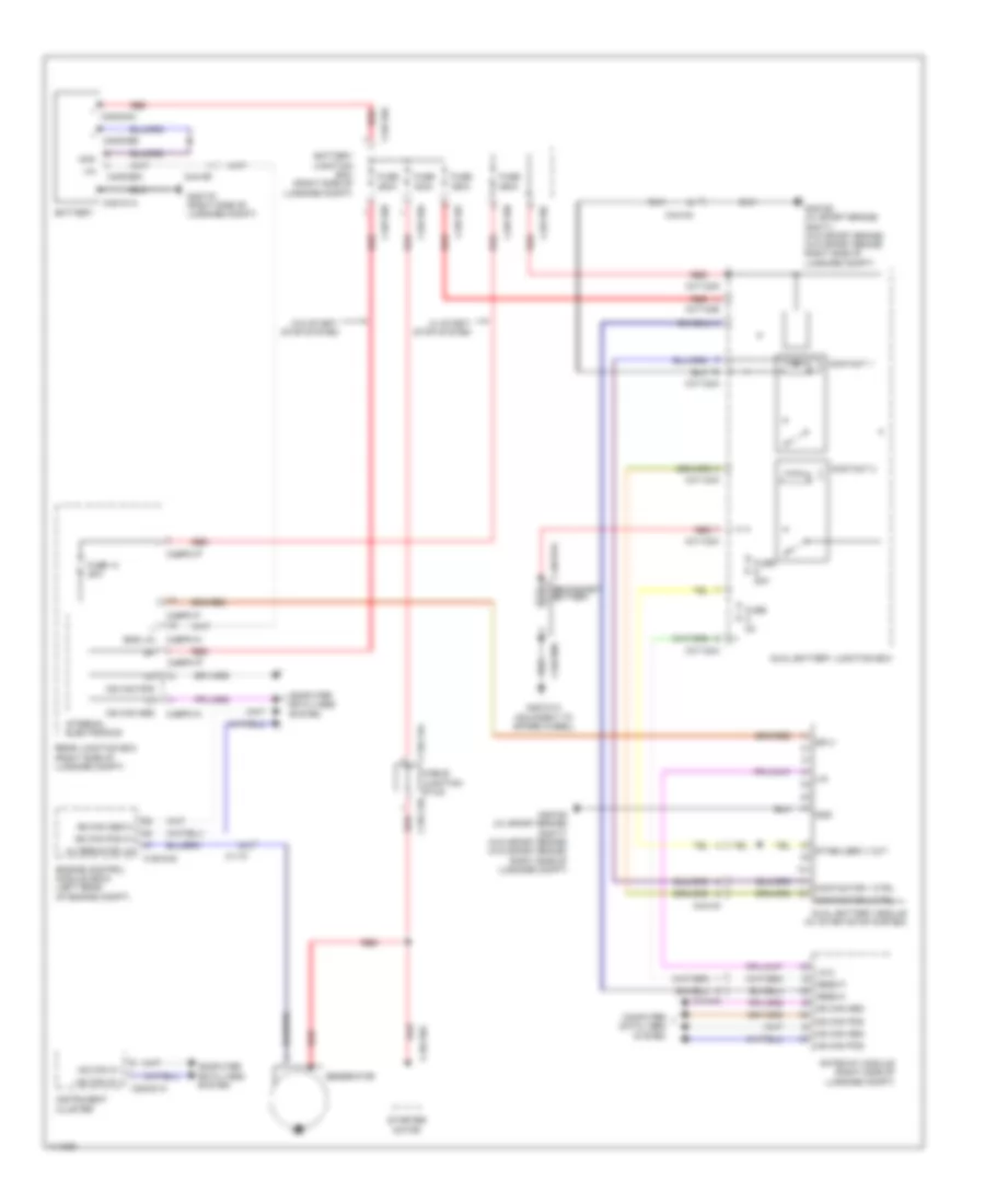
2.0L Turbo, Charging Wiring Diagram for Jaguar XF Supercharged 2013

List of elements for 2.0L Turbo, Charging Wiring Diagram for Jaguar XF Supercharged 2013:
- + c4dc02a
- + c4dc05b
- Alternator lin
- Battery
- Battery junction box (right side of luggage compt)
- Bms lin
- C11-p
- C1dc12a
- C1dc12b
- C1dc35a
- C1e104c
- C2mc01a
- C44-aa
- C44-ar
- C4bf10a
- C4bf10b
- C4bf10f
- C4bp01f
- C4bp01k
- C4bp01p
- C4d101a
- C4dc80a
- C4dc81a secondary battery
- C4dco5a
- C4df10a
- C4df10c
- C4y124a
- C4y124c
- C4y124d
- C4y124e
- Cable junction stud
- Computer data lines system
- Contact 1
- Contact 2
- Contactor 1 ctrl
- Contactor 2 ctrl
- Dual battery junction box
- Dual battery module (w/ start/stop system)
- Engine control module (ecm) (left rear of engine compt)
- Fuse 14 20a
- Fuse 20a
- Fuse 250a
- Fuse 350a
- Fuse 400a
- Fuse 5a
- G4d101a (adjacent to spare wheel)
- G4d152 (w/ sport brake) g4d171 (w/o sport brake) (w/o sport brake: right side of luggage compt)
- G4d178 (right side of luggage compt)
- Gateway module (right side of luggage compt)
- Generator
- Gnd
- Hs can in +
- Hs can in -
- Hs can pos
- Hs can pos c+
- Instrument cluster
- Internal electronics
- Lin
- Lin 2
- Mess m
- Mess p
- Mon
- Ms can pos
- Rear junction box (right side of luggage compt)
- Red
- Sply
- Stabilized v out
- Starter motor
- W/ start/ stop system
- W/o start/ stop system
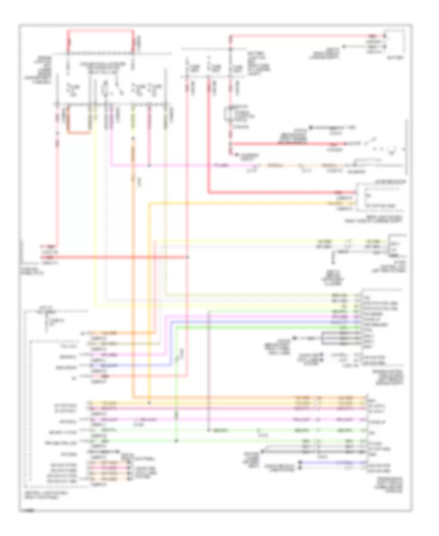
2.0L Turbo, Starting Wiring Diagram for Jaguar XF Supercharged 2013
List of elements for 2.0L Turbo, Starting Wiring Diagram for Jaguar XF Supercharged 2013:
- (behind instrument cluster) g2d115
- All times
- Battery
- Battery junction box (right side of luggage compt)
- C11-p
- C13-e
- C1bb01b
- C1d101
- C1dc12a
- C1dc12b
- C1dc35a
- C1dc71b
- C1dc71c
- C1e105b
- C23-d
- C33-c
- C3bp01
- C3bp01c
- C3bp01d
- C3bp01g
- C3bp01k
- C3bp01m
- C4bf10a
- C4bf10b
- C4bpo1m
- C4bpo1p
- C4d101a
- C4d102a
- Cable junction stud
- Central junction box (right kick panel)
- Charging circuit
- Computer data lines system
- Conventional starter/tss pinion relay (full iso)
- Crank req
- Emc ewu
- Eng crank
- Engine control module (ecm) (left rear of engine compt)
- Engine junction box (under engine compartment fuse box)
- Fuse 250a
- Fuse 30a
- Fuse 400a
- Fuse 5a
- G1d108 (behind right front wheel arch liner)
- G1d124 (behind right front fender splash shield)
- G3d138 (right kick panel)
- G3d182b (under driver's seat)
- G4d178 (right side of luggage compt)
- Gnd
- Gnd 1
- Hot at
- Hot at all times
- Hs can pos
- Ihu lin 2
- Internal electronics
- Lin
- Motor
- Ms can pos
- P gnd
- P n sig
- Rear junction box (right side of luggage compt)
- Red
- Sply
- St stp sw
- Start control unit (left end of dash)
- Start stop 1
- Start stop sw 1
- Start stop sw 2
- Starter motor
- Stop start 2
- Stren
- Strth
- Strtl
- Transmission shift module (under center console)
- Wake up
3.0L SC
3.0L SC, Charging Wiring Diagram for Jaguar XF Supercharged 2013
List of elements for 3.0L SC, Charging Wiring Diagram for Jaguar XF Supercharged 2013:
- + c4dc02a
- + c4dc05b
- Alternator lin
- Battery
- Battery junction box (right side of luggage compt)
- Bms lin
- C11-p
- C1dc12a
- C1dc12b
- C1dc35a
- C1e104c
- C2mc01a
- C44-aa
- C44-ar
- C4bf10a
- C4bf10b
- C4bf10f
- C4bp01f
- C4bp01k
- C4bp01p
- C4d101a
- C4dc80a
- C4dc81a secondary battery
- C4dco5a
- C4df10a
- C4df10c
- C4y124a
- C4y124c
- C4y124d
- C4y124e
- Cable junction stud
- Computer data lines system
- Contact 1
- Contact 2
- Contactor 1 ctrl
- Contactor 2 ctrl
- Dual battery junction box
- Dual battery module (w/ start/stop system)
- Engine control module (ecm) (left rear of engine compt)
- Fuse 14 20a
- Fuse 20a
- Fuse 250a
- Fuse 350a
- Fuse 400a
- Fuse 5a
- G4d101a (adjacent to spare wheel)
- G4d152 (w/ sport brake) g4d171 (w/o sport brake) (w/o sport brake: right side of luggage compt)
- G4d178 (right side of luggage compt)
- Gateway module (right side of luggage compt)
- Generator
- Gnd
- Hs can in +
- Hs can in -
- Hs can pos
- Hs can pos c+
- Instrument cluster
- Internal electronics
- Lin
- Lin 2
- Mess m
- Mess p
- Mon
- Ms can pos
- Rear junction box (right side of luggage compt)
- Red
- Sply
- Stabilized v out
- Starter motor
- W/ start/ stop system
- W/o start/ stop system
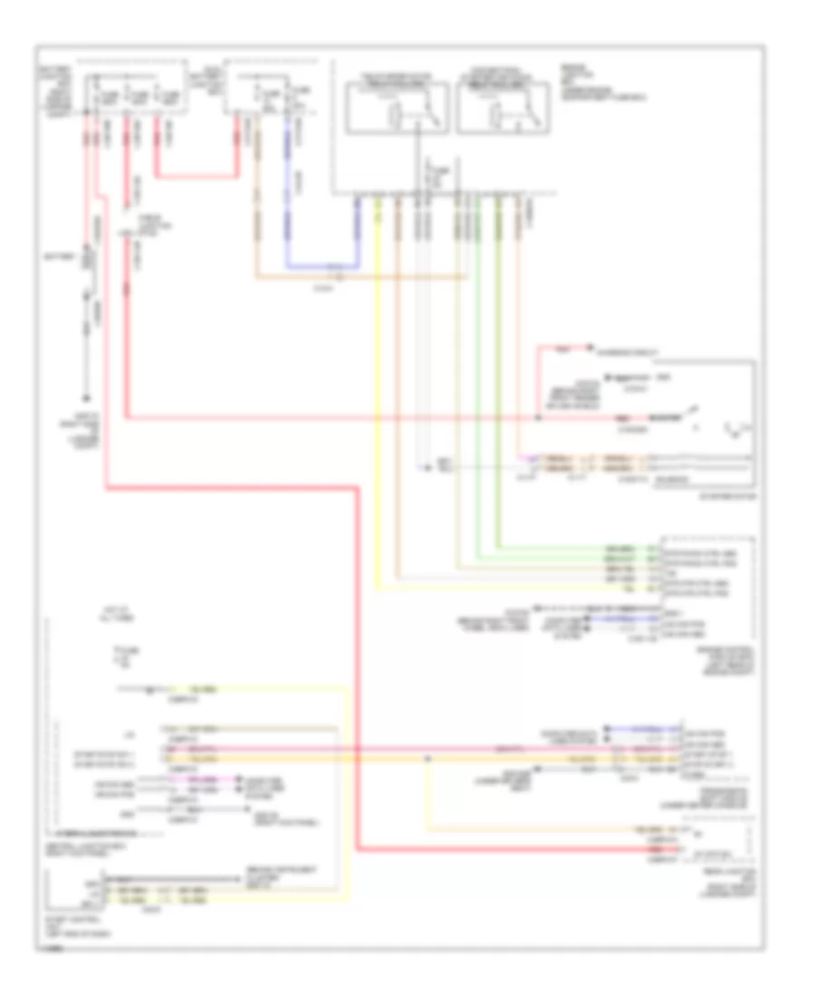
3.0L SC, Starting Wiring Diagram, with Start-Stop System for Jaguar XF Supercharged 2013
List of elements for 3.0L SC, Starting Wiring Diagram, with Start-Stop System for Jaguar XF Supercharged 2013:
- (behind instrument cluster) g2d115
- All times
- Battery
- Battery junction box (right side of luggage compt)
- C11-p
- C11-t
- C13-h
- C1bb01b
- C1d101
- C1dc12a
- C1dc12b
- C1dc35a
- C1dc71a
- C1e111b
- C23-d
- C33-c
- C3bp01c
- C3bp01d
- C3bp01k
- C3bp01m
- C4010ia
- C44-ab
- C4bf10a
- C4bf10b
- C4bf10f
- C4bpo1m
- C4bpo1p
- C4dc02a
- C4y124b
- C4y124e
- Cable junction stud
- Central junction box (right kick panel)
- Charging circuit
- Computer data lines system
- Conventional starter/tss pinion relay (full iso)
- Dual battery junction box
- Engine control module (ecm) (left rear of engine compt)
- Engine junction box (under engine compartment fuse box)
- Fuse 20a
- Fuse 250a
- Fuse 350a
- Fuse 400a
- Fuse 40a
- Fuse 5a
- G1d108 (behind right front wheel arch liner)
- G1d124 (behind right front fender splash shield)
- G3d138 (right kick panel)
- G3d182b (under driver's seat)
- G4d178 (right side of luggage compt)
- Gnd
- Gnd 1
- Hot at
- Hs can pos
- Internal electronics
- Lin
- Motor
- Ms can pos
- P gnd
- Rear junction box (right side of luggage compt)
- Red
- Solenoid
- Sply
- St stp sw
- Start control unit (left end of dash)
- Start stop 1
- Start stop sw 1
- Start stop sw 2
- Starter motor
- Stop start 2
- Str mtr ctrl pos
- Str pinion ctrl pos
- T50
- Transmission shift module (under center console)
- Tss starter motor relay (full iso)
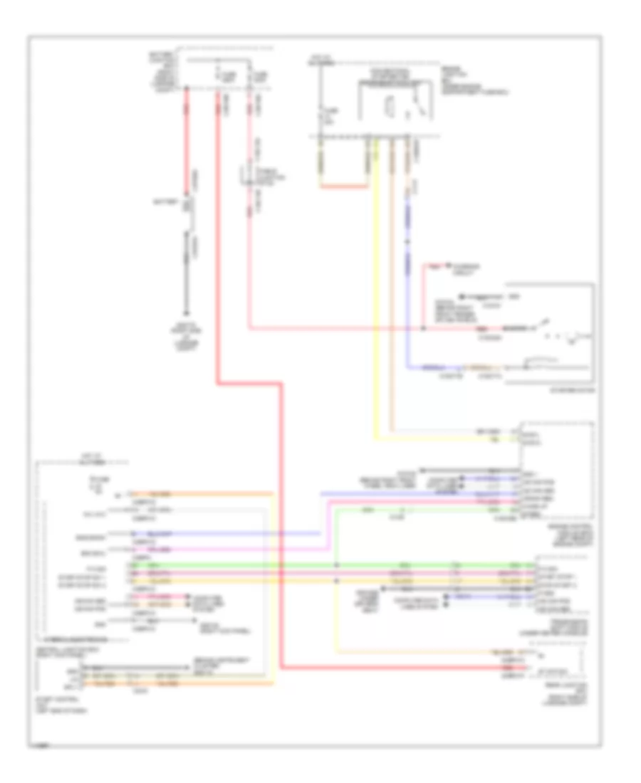
3.0L SC, Starting Wiring Diagram, without Start-Stop System for Jaguar XF Supercharged 2013
List of elements for 3.0L SC, Starting Wiring Diagram, without Start-Stop System for Jaguar XF Supercharged 2013:
- Bat
- Battery
- Battery junction box (right side of luggage compt)
- C11-p
- C11-t
- C13-b
- C13-c
- C13-e
- C1bb01b
- C1bb01c
- C1d101
- C1dc11b
- C1dc12a
- C1dc12b
- C1dc35a
- C1dc71c
- C1e111b
- C23-d
- C33-c
- C3bp01c
- C3bp01d
- C3bp01e
- C3bp01g
- C3bp01j
- C3bp01k
- C3bp01m
- C3bp01p
- C3dc11a
- C4bf10a
- C4bf10b
- C4bf10c
- C4bp01m
- C4bp01p
- C4d101a
- C4dc02a
- Cable junction stud
- Central junction box (right kick panel)
- Charging circuit
- Computer data lines system
- Conventional starter tss pinion motor relay (full iso)
- Crk request
- Ems ewu
- Eng crank
- Engine control module (ecm) (left rear of engine compt)
- Engine junction box (under engine compartment fuse box)
- Ets ewu
- Fuse 10a
- Fuse 250a
- Fuse 30a
- Fuse 34 5a
- Fuse 400a
- Fuse 5a
- G1d108 (behind right front wheel arch liner)
- G1d124 (behind right front fender splash shield)
- G2d115 (behind instrument cluster)
- G3d138 (right kick panel)
- G3d182b (under driver's seat)
- G4d178 (right side of luggage compt)
- Gnd
- Gnd 1
- Gnd 2
- Gnd 3
- Hot at all times
- Hs can pos
- Ign
- Ign sense
- Ign sply 2 fwd
- Lin
- Motor
- Ms can in pos
- Ms can out pos
- Ntrl
- P n sig
- Prk neutral sig
- Rear junction box (right side of luggage compt)
- Red
- Solenoid
- Sply
- St stp 1
- St stp 2
- St stp gnd
- St stp sw sns
- St stp sw1
- St stp sw2
- Start control unit (left end of dash)
- Starter motor
- Str mtr ctrl pos
- Sys gnd
- T50
- Tap1 1
- Tap1 2
- Tau lin 2
- Through panel stud
- Transmission shift module (under center console)
- Wake up
5.0L SC
5.0L SC, Charging Wiring Diagram for Jaguar XF Supercharged 2013
List of elements for 5.0L SC, Charging Wiring Diagram for Jaguar XF Supercharged 2013:
- + c4dc02a
- + c4dc05b
- Alternator lin
- Battery
- Battery junction box (right side of luggage compt)
- Bms lin
- C11-p
- C1dc12a
- C1dc12b
- C1dc35a
- C1e104c
- C2mc01a
- C44-aa
- C44-ar
- C4bf10a
- C4bf10b
- C4bf10f
- C4bp01f
- C4bp01k
- C4bp01p
- C4d101a
- C4dc80a
- C4dc81a secondary battery
- C4dco5a
- C4df10a
- C4df10c
- C4y124a
- C4y124c
- C4y124d
- C4y124e
- Cable junction stud
- Computer data lines system
- Contact 1
- Contact 2
- Contactor 1 ctrl
- Contactor 2 ctrl
- Dual battery junction box
- Dual battery module (w/ start/stop system)
- Engine control module (ecm) (left rear of engine compt)
- Fuse 14 20a
- Fuse 20a
- Fuse 250a
- Fuse 350a
- Fuse 400a
- Fuse 5a
- G4d101a (adjacent to spare wheel)
- G4d152 (w/ sport brake) g4d171 (w/o sport brake) (w/o sport brake: right side of luggage compt)
- G4d178 (right side of luggage compt)
- Gateway module (right side of luggage compt)
- Generator
- Gnd
- Hs can in +
- Hs can in -
- Hs can pos
- Hs can pos c+
- Instrument cluster
- Internal electronics
- Lin
- Lin 2
- Mess m
- Mess p
- Mon
- Ms can pos
- Rear junction box (right side of luggage compt)
- Red
- Sply
- Stabilized v out
- Starter motor
- W/ start/ stop system
- W/o start/ stop system
5.0L SC, Starting Wiring Diagram, with Start-Stop System for Jaguar XF Supercharged 2013
List of elements for 5.0L SC, Starting Wiring Diagram, with Start-Stop System for Jaguar XF Supercharged 2013:
- (behind instrument cluster) g2d115
- All times
- Battery
- Battery junction box (right side of luggage compt)
- C11-p
- C11-t
- C13-h
- C1bb01b
- C1d101
- C1dc12a
- C1dc12b
- C1dc35a
- C1dc71a
- C1e111b
- C23-d
- C33-c
- C3bp01c
- C3bp01d
- C3bp01k
- C3bp01m
- C4010ia
- C44-ab
- C4bf10a
- C4bf10b
- C4bf10f
- C4bpo1m
- C4bpo1p
- C4dc02a
- C4y124b
- C4y124e
- Cable junction stud
- Central junction box (right kick panel)
- Charging circuit
- Computer data lines system
- Conventional starter/tss pinion relay (full iso)
- Dual battery junction box
- Engine control module (ecm) (left rear of engine compt)
- Engine junction box (under engine compartment fuse box)
- Fuse 20a
- Fuse 250a
- Fuse 350a
- Fuse 400a
- Fuse 40a
- Fuse 5a
- G1d108 (behind right front wheel arch liner)
- G1d124 (behind right front fender splash shield)
- G3d138 (right kick panel)
- G3d182b (under driver's seat)
- G4d178 (right side of luggage compt)
- Gnd
- Gnd 1
- Hot at
- Hs can pos
- Internal electronics
- Lin
- Motor
- Ms can pos
- P gnd
- Rear junction box (right side of luggage compt)
- Red
- Solenoid
- Sply
- St stp sw
- Start control unit (left end of dash)
- Start stop 1
- Start stop sw 1
- Start stop sw 2
- Starter motor
- Stop start 2
- Str mtr ctrl pos
- Str pinion ctrl pos
- T50
- Transmission shift module (under center console)
- Tss starter motor relay (full iso)
5.0L SC, Starting Wiring Diagram, without Start-Stop System for Jaguar XF Supercharged 2013
List of elements for 5.0L SC, Starting Wiring Diagram, without Start-Stop System for Jaguar XF Supercharged 2013:
- Bat
- Battery
- Battery junction box (right side of luggage compt)
- C11-p
- C11-t
- C13-b
- C13-c
- C13-e
- C1bb01b
- C1bb01c
- C1d101
- C1dc11b
- C1dc12a
- C1dc12b
- C1dc35a
- C1dc71c
- C1e111b
- C23-d
- C33-c
- C3bp01c
- C3bp01d
- C3bp01e
- C3bp01g
- C3bp01j
- C3bp01k
- C3bp01m
- C3bp01p
- C3dc11a
- C4bf10a
- C4bf10b
- C4bf10c
- C4bp01m
- C4bp01p
- C4d101a
- C4dc02a
- Cable junction stud
- Central junction box (right kick panel)
- Charging circuit
- Computer data lines system
- Conventional starter tss pinion motor relay (full iso)
- Crk request
- Ems ewu
- Eng crank
- Engine control module (ecm) (left rear of engine compt)
- Engine junction box (under engine compartment fuse box)
- Ets ewu
- Fuse 10a
- Fuse 250a
- Fuse 30a
- Fuse 34 5a
- Fuse 400a
- Fuse 5a
- G1d108 (behind right front wheel arch liner)
- G1d124 (behind right front fender splash shield)
- G2d115 (behind instrument cluster)
- G3d138 (right kick panel)
- G3d182b (under driver's seat)
- G4d178 (right side of luggage compt)
- Gnd
- Gnd 1
- Gnd 2
- Gnd 3
- Hot at all times
- Hs can pos
- Ign
- Ign sense
- Ign sply 2 fwd
- Lin
- Motor
- Ms can in pos
- Ms can out pos
- Ntrl
- P n sig
- Prk neutral sig
- Rear junction box (right side of luggage compt)
- Red
- Solenoid
- Sply
- St stp 1
- St stp 2
- St stp gnd
- St stp sw sns
- St stp sw1
- St stp sw2
- Start control unit (left end of dash)
- Starter motor
- Str mtr ctrl pos
- Sys gnd
- T50
- Tap1 1
- Tap1 2
- Tau lin 2
- Through panel stud
- Transmission shift module (under center console)
- Wake up