STARTING/CHARGING
4.0L
4.0L, Charging Wiring Diagram for Jaguar XJ6 1997

List of elements for 4.0L, Charging Wiring Diagram for Jaguar XJ6 1997:
- (battery ground stud) g401
- (front bulkhead) center terminal
- 1996 vftc c
- 250a
- Battery (trunk)
- Charge indicator
- Fc10
- Fuse 10 5a
- Generator (left side of engine)
- Hot in run & start
- Instrument pack
- Power fuses (on positive battery post)
- Right engine bay fuse box
- Rs1
- St2
- St5 st3
- St8
- Starter motor (left rear of engine)
- Suppression module (left front engine bay)
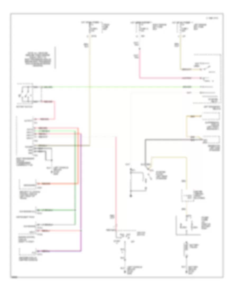
4.0L, Starting Wiring Diagram for Jaguar XJ6 1997
List of elements for 4.0L, Starting Wiring Diagram for Jaguar XJ6 1997:
- (battery ground stud) g401
- (left console ground stud) g206
- (not used)
- 1996 vftc c
- 250a
- Acc
- An1/ st4
- Arm/disarm
- Battery (trunk)
- Body processor module (passenger's underscuttle)
- Bt35
- Ca21
- Cc13
- Center terminal (front bulkhead)
- Chk engine
- Chk engine (mil)
- Data
- Decoder module (center console)
- Engine control module (right "a" post)
- Fc1
- Fc10
- Fc2
- Fc3
- Fuse 12 10a
- Fuse 3 25a
- Fuse 5 10a
- Generator (left side of engine)
- Gnd
- Hot at all times
- Hot in run & start
- Ignition switch
- Iii
- Input
- Instrument pack
- Left engine bay fuse box
- Left engine bay relays
- Ls1
- Nca
- Note: all vehicles require "check engine" signal input to body processor module before body processor module enables engine cranking
- Off
- Output
- P,n
- Pi104
- Pi105
- Power
- Power fuses (on positive battery post)
- Right engine bay fuse box
- Rotary switch
- Rs1
- Run
- Security & locking control module (left front of trunk)
- St1
- St2
- St5 st3
- St8
- Start
- Starter motor (left rear of engine)
- Starter relay
- Suppression module (left front engine bay)
- Trunk fuse box