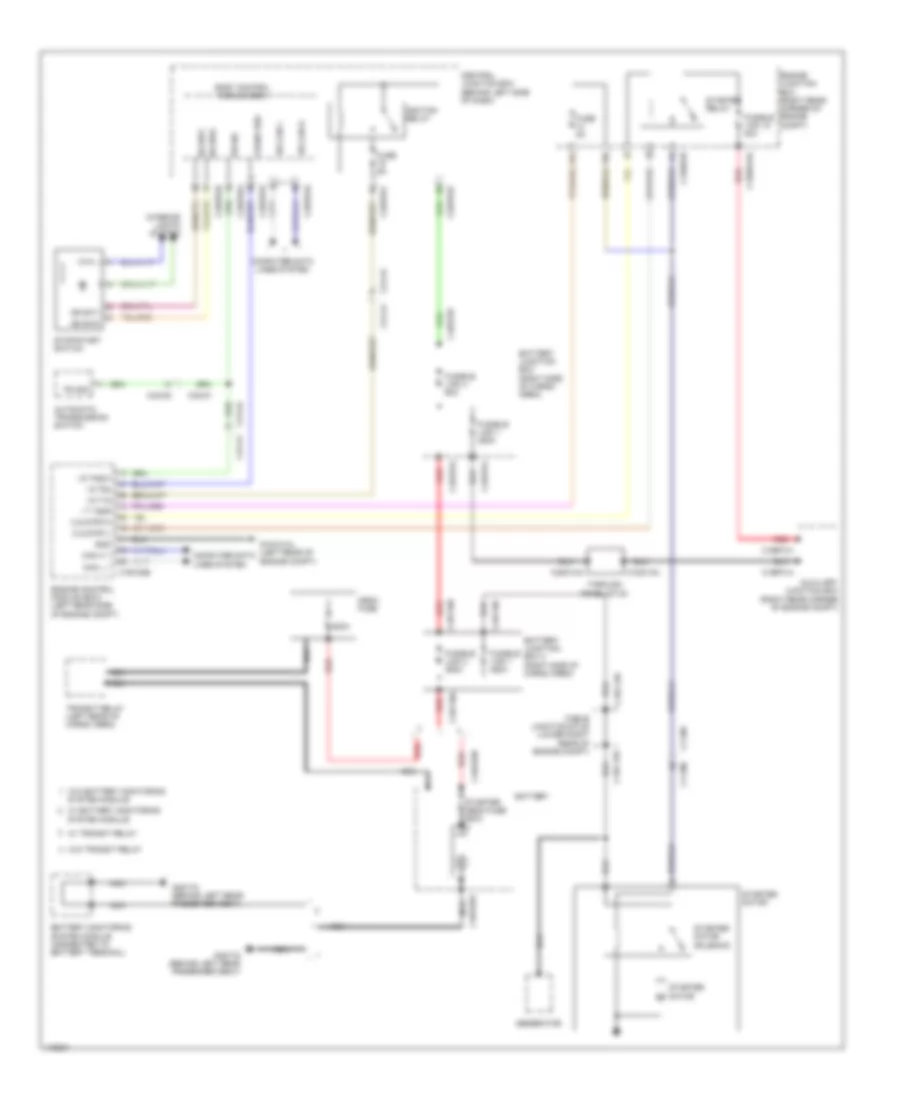
AUTOMOTIVE ELECTRICIANS PORTAL

STARTING/CHARGING – Land Rover Range Rover Autobiography 2013 – SYSTEM WIRING DIAGRAMS

STARTING/CHARGING

Charging Wiring Diagram for Land Rover Range Rover Autobiography 2013

Charging Wiring Diagram for Land Rover Range Rover Autobiography 2013 https://portal-diagnostov.com/license.html
https://portal-diagnostov.com/license.html Automotive Electricians Portal FZCO Automotive Electricians Portal FZCO
Download PDF file

List of elements for Charging Wiring Diagram for Land Rover Range Rover Autobiography 2013:

  • 500a
  • Battery
  • Battery junction box 2 (right side of cargo area)
  • Battery monitoring system module (connected to battery terminal)
  • C11-m1
  • C11-m2
  • C12-a1
  • C12-a2
  • C1dc12b
  • C1dc12g
  • C2mc01a
  • C4dc02b
  • C4dc03a
  • C4dc27
  • C4dc56b
  • C4df10a
  • C4df10c
  • Cable junction stud (lower right rear of c1dc12e engine compt)
  • Computer data lines system
  • Fusible link 1 450a
  • Fusible wire link
  • G4d150d (on right side of cargo area)
  • G4d178 (behind left rear passenger seat)
  • Gateway module (behind right side of dash)
  • Generator
  • Hs can h
  • Hs can l
  • Instrument cluster
  • Jump start terminal (right side of engine compt)
  • Lin
  • Lin 3
  • Mega fuse
  • Mon
  • Nca
  • Red
  • Starter mega fuse 500a
  • Starter motor
  • System module
  • Transit relay (left rear of cargo area)
  • W/ battery monitoring
  • W/ transit relay
  • W/o battery monitoring
  • W/o transit relay

Starting Wiring Diagram for Land Rover Range Rover Autobiography 2013

Starting Wiring Diagram for Land Rover Range Rover Autobiography 2013 https://portal-diagnostov.com/license.html
https://portal-diagnostov.com/license.html Automotive Electricians Portal FZCO Automotive Electricians Portal FZCO
获取访问所有汽车的接线图Download PDF file

List of elements for Starting Wiring Diagram for Land Rover Range Rover Autobiography 2013:

  • 500a
  • Automatic transmission switch
  • Auxiliary junction box (right rear corner of engine compt)
  • Battery
  • Battery junction box (right side of cargo area)
  • Battery junction box 2 (right side of cargo area)
  • Battery monitoring system module (connected to battery terminal)
  • Body control module (bcm)
  • C11-m1
  • C11-m2
  • C1bb01aa
  • C1bb01b
  • C1bf01a
  • C1bf01h
  • C1dc12b
  • C1dc12e
  • C1dc13a
  • C1e120b
  • C2bp01b
  • C2bp01d
  • C2bp01e
  • C2bp01f
  • C2bp01g
  • C31-a1
  • C31-a2
  • C31-a2 c31-a1
  • C32-m1
  • C32-m2
  • C3dc13a
  • C4bf01a
  • C4bf01d
  • C4bf01j
  • C4dc02b
  • C4dc03a
  • C4df10a
  • C4df10c
  • C4df10e
  • Cable junction stud (lower right rear of engine compt)
  • Can h 1
  • Can l 1
  • Central junction box (behind left side of dash)
  • Computer data lines system
  • Crank req
  • Engine control module (ecm) (left rear side of engine compt)
  • Engine junction box (right rear corner of engine compt)
  • Fuse 5a
  • Fusible link 1 250a
  • Fusible link 1 450a
  • Fusible link 15 40a
  • Fusible link 2 350a
  • Fusible link 4 60a
  • G1d121al (left rear of engine compt)
  • G4d178 (behind left rear passenger seat)
  • Generator
  • Gnd
  • Hs can h
  • Hs can l
  • I s t15
  • I s t50
  • I s tnsw
  • I t t50r
  • Ignition relay
  • Interior lights system
  • Mega fuse
  • Nca
  • O s strth
  • O s strtl
  • Pn sig
  • Red
  • Ss sw1
  • Ss sw2
  • Starter mega fuse 500a
  • Starter motor
  • Starter motor solenoid
  • Starter relay
  • Stop/start switch
  • System module
  • Through panel stud
  • Transit relay (left rear of cargo area)
  • W/ battery monitoring system module
  • W/ transit relay
  • W/o battery monitoring
  • W/o transit relay