STARTING/CHARGING
3.0L TURBO DIESEL
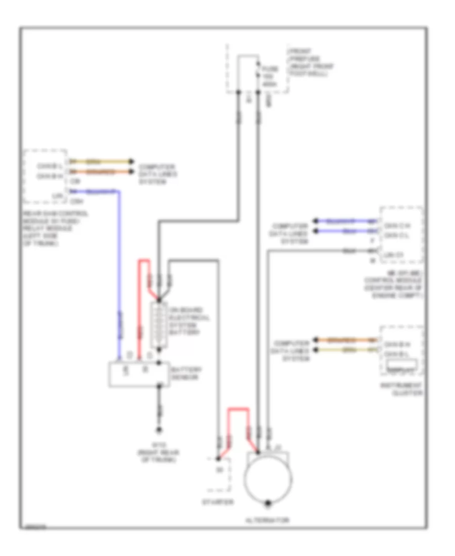
3.0L Turbo Diesel, Charging Wiring Diagram, Sedan for Mercedes-Benz E350 2011

List of elements for 3.0L Turbo Diesel, Charging Wiring Diagram, Sedan for Mercedes-Benz E350 2011:
- Alternator
- Battery sensor
- C5h
- C9i
- Can b h
- Can b l
- Can c h
- Can c l
- Cdi control module (left rear of engine compt)
- Computer data lines system
- Display
- Front prefuse (right front footwell)
- Fuse 150a
- Fuse 400a
- Glow output stage
- Instrument cluster
- Lin
- Lin c1
- Mr8
- Nca
- On board electrical system battery (front battery)
- Rear sam control module w/ fuse/ relay module (left side of trunk)
- Red
- Starter
- W10 (right rear of trunk)
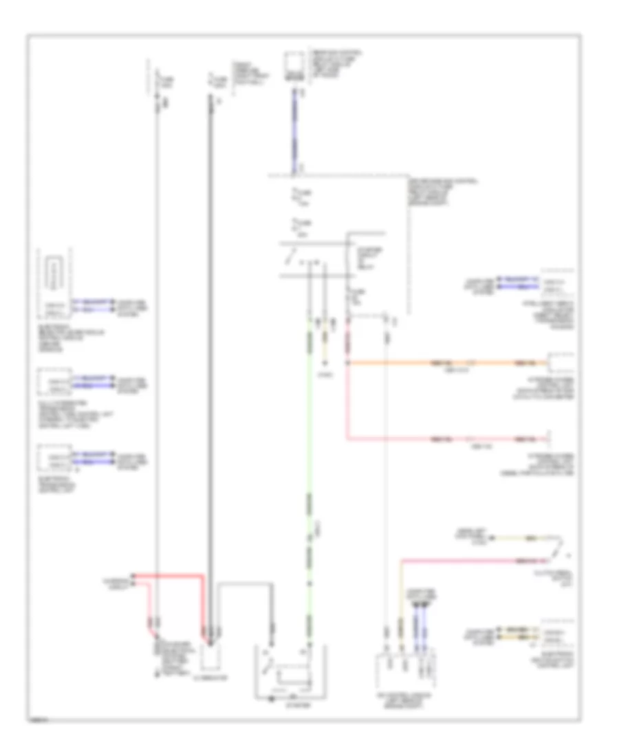
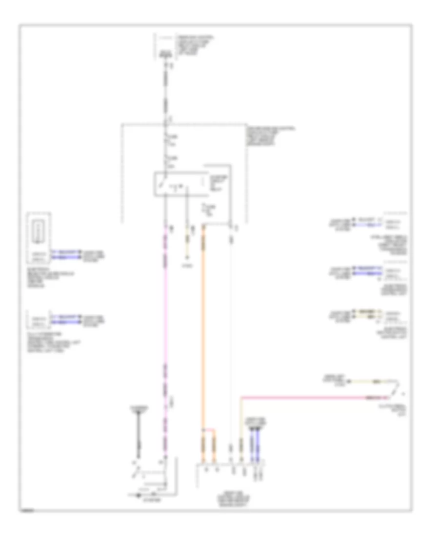
3.0L Turbo Diesel, Starting Wiring Diagram, Sedan for Mercedes-Benz E350 2011
List of elements for 3.0L Turbo Diesel, Starting Wiring Diagram, Sedan for Mercedes-Benz E350 2011:
- (near left kick panel) w15/2
- Alternator
- C15m
- C3m
- C4i
- C7i
- C9i
- Can b h
- Can b l
- Can c h
- Can c l
- Cdi control module (left rear of engine compt)
- Charging circuit
- Clutch pedal switch (m/t)
- Computer data lines system
- Driver side sam control module w/ fuse/ relay module (left rear of engine compt)
- Electronic ignition switch control unit
- Electronic selector lever module control module (center console)
- Electronic transmission control unit
- Front prefuse (right front footwell)
- Fully integrated transmission control (vgs) control unit (integral to electric control unit (vgs))
- Fuse 150a
- Fuse 15a
- Fuse 20a
- Fuse 400a
- Fuse 7.5a
- Intelligent servo module for direct select (transmission housing)
- Kup1
- Mr8
- Nca
- Nitrogen oxides control unit down stream of diesel particulate filter
- Nitrogen oxides control unit down stream of scr catalytic converter
- On board electrical system battery (front battery)
- P r n d- d+
- Rear sam control module w/ fuse/ relay module (left side of trunk)
- Red
- Solid state
- Starter
- Starter circuit relay
- Str
- W16/3
- X26-c1
- X86/1-c1a
- X86/1-c2
3.5L
3.5L, Charging Wiring Diagram, Coupe for Mercedes-Benz E350 2011
List of elements for 3.5L, Charging Wiring Diagram, Coupe for Mercedes-Benz E350 2011:
- Alternator
- Battery sensor
- C5h
- C9i
- Can b h
- Can b l
- Can c h
- Can c l
- Computer data lines system
- Display
- Front prefuse (right front footwell)
- Fuse 400a
- Instrument cluster
- Lin
- Lin c1
- Me-sfi (me) control module (center rear of engine compt)
- Mr8
- On board electrical system battery
- Rear sam control module w/ fuse/ relay module (left side of trunk)
- Red
- Starter
- W10 (right rear of trunk)
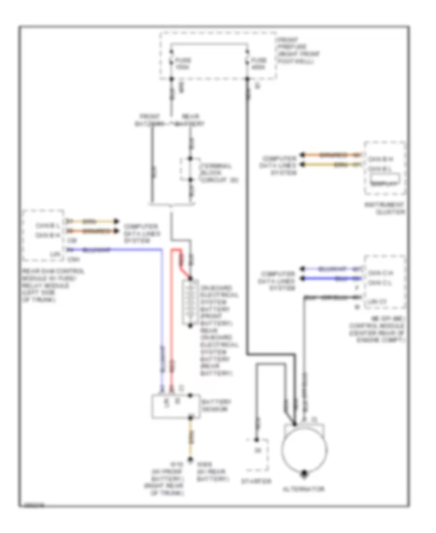
3.5L, Charging Wiring Diagram, Sedan for Mercedes-Benz E350 2011
List of elements for 3.5L, Charging Wiring Diagram, Sedan for Mercedes-Benz E350 2011:
- Alternator
- Battery sensor
- C5h
- C9i
- Can b h
- Can b l
- Can c h
- Can c l
- Computer data lines system
- Display
- Front battery
- Front prefuse (right front footwell)
- Fuse 150a
- Fuse 400a
- Instrument cluster
- Lin
- Lin c1
- Me-sfi (me) control module (center rear of engine compt)
- Mr8
- Nca
- On board electrical system battery (front battery) rear on board electrical system battery (rear battery)
- Rear battery
- Rear sam control module w/ fuse/ relay module (left side of trunk)
- Red
- Starter
- Terminal block (circuit 30)
- W10 (w/ front battery) (right rear of trunk)
- W8/8 (w/ rear battery)
3.5L, Starting Wiring Diagram, Coupe for Mercedes-Benz E350 2011
List of elements for 3.5L, Starting Wiring Diagram, Coupe for Mercedes-Benz E350 2011:
- Battery sensor
- C15m
- C3m
- C4i
- C9i
- Can b h
- Can b l
- Can c h
- Can c l
- Charging circuit
- Computer data lines system
- Driver side sam control module w/ fuse/ relay module (left rear of engine compt)
- Electronic ignition switch control unit
- Electronic selector lever module control module (center console)
- Fully integrated transmission control (vgs) control unit (integral to electric control unit (vgs))
- Fuse 15a
- Fuse 20a
- Fuse 7.5a
- Kup2
- Me-sfi (me) control module (center rear of engine compt)
- On board electrical system battery
- P r n d- d+
- Pnk/red
- Power distribution system
- Rear sam control module w/ fuse/ relay module (left side of trunk)
- Red
- Solid state
- Start enable clutch pedal switch (m/t)
- Starter
- Starter circuit relay
- W10 (right rear of trunk)
- W16/3
- X26-c1
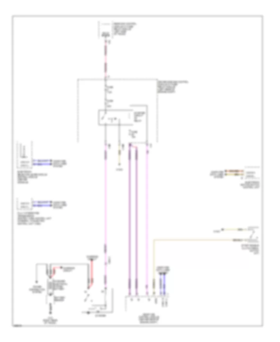
3.5L, Starting Wiring Diagram, Sedan for Mercedes-Benz E350 2011
List of elements for 3.5L, Starting Wiring Diagram, Sedan for Mercedes-Benz E350 2011:
- (near left kick panel) w15/2
- C15m
- C3m
- C4i
- C7i
- C9i
- Can b h
- Can b l
- Can c h
- Can c l
- Charging circuit
- Clutch pedal switch (m/t)
- Computer data lines system
- Driver side sam control module w/ fuse / relay module (left rear of engine compt)
- Electronic ignition switch control unit
- Electronic selector lever module control module (center console)
- Electronic transmission control unit
- Fully integrated transmission control (vgs) control unit (integral to electric control unit (vgs))
- Fuse 15a
- Fuse 20a
- Fuse 7.5a
- Intelligent servo module for direct select (transmission housing)
- Kup1
- Me-sfi (me) control module (center rear of engine compt)
- Nca
- P r n d- d+
- Rear sam control module w/ fuse/ relay module (left side of trunk)
- Solid state
- Starter
- Starter circuit relay
- Str
- W16/3
- X26-c1