STARTING/CHARGING
Charging Wiring Diagram for Mercedes-Benz ML350 4Matic 2014

List of elements for Charging Wiring Diagram for Mercedes-Benz ML350 4Matic 2014:
- (front of right cylinder bank) glow output stage
- (near eco start/stop function additional battery) (if equipped) eco start/stop function additional battery relay
- (or nca)
- (under front passenger's seat) w10
- 10a
- 3.0l turbo diesel
- 3.5l & 4.6l turbo
- Alternator
- Bub-l-el
- Bub-m
- Buffer battery fuse (right rear of luggage compt)
- Can a h
- Can a l
- Can b h
- Can b l
- Can c h
- Can c l
- Cdi control unit (rear of right front fender)
- Computer data lines system
- Display
- E1b
- E2b
- Eco start/stop function additional battery
- Eco start/stop function diode (right rear of engine compt)
- Electronic ignition switch control unit
- Engine compartment prefuse box (right rear of engine compt)
- Instrument cluster
- Interior prefuse box (right front upper footwell)
- Lin b15
- Lin c1
- Me-sfi (me) control unit (3.5l: left side of engine) (4.6l turbo: top center rear of engine)
- Nca
- On-board electrical system battery
- Pb-30b
- Power distribution system
- Rear fuse box (in right rear footwell)
- Red
- Rel bub
- Rel ek
- Sam control unit (right kick panel)
- Starter
- W10/15 (right rear of luggage compt)
- W15/1 (right front footwell)
- W7 (base of right "d" pillar)
- X18-c1
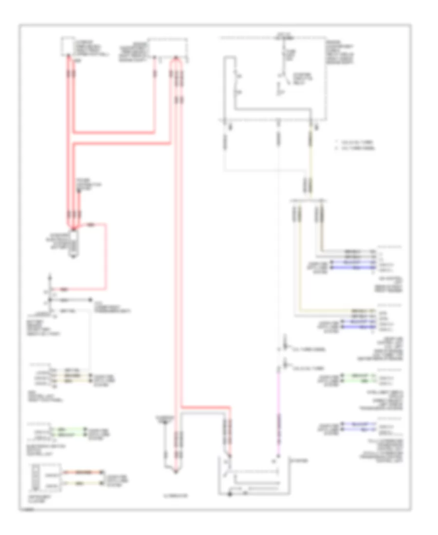
Starting Wiring Diagram for Mercedes-Benz ML350 4Matic 2014
List of elements for Starting Wiring Diagram for Mercedes-Benz ML350 4Matic 2014:
- (+)
- (-)
- (or nca)
- 3.0l turbo diesel
- 3.5l & 4.6l turbo
- Alternator
- Can a h
- Can a l
- Can b h
- Can b l
- Can c h
- Can c l
- Cdi control unit (rear of right front fender)
- Charging circuit
- Computer data lines system
- E2b
- Electronic ignition switch control unit
- Engine compartment fuse & relay module (right side of engine compt)
- Engine compartment prefuse box (right rear of engine compt)
- Fully integrated transmission control unit (in fully integrated transmission control control unit)
- Fuse 240a 30a
- Hot at all times
- Instrument cluster
- Intelligent servo module (direct select) (left side of transmission housing)
- Interior prefuse box (right front upper footwell)
- Lin b15
- Me-sfi (me) control unit (3.5l: left side of engine) (4.6l turbo: top center rear of engine)
- Mr1
- Mr2
- Nca
- On-board electrical system battery
- P r n d s
- Power distribution system
- Red
- Sam control unit (right kick panel)
- Starter
- Starter circuit 50 relay
- Str
- Str+
- W10 (under front passenger's seat)
- X26-c1
- X26/31-c1