STARTING/CHARGING
Charging Wiring Diagram for Mercedes-Benz R500 2007

List of elements for Charging Wiring Diagram for Mercedes-Benz R500 2007:
- 3.5l
- 5.5l
- Auxiliary battery
- Battery
- Battery compartment prefuse box (under right rear footwell)
- C14b
- C5e
- C86
- Can-c h
- Can-c l
- Cdi control module (left front of engine compt)
- Cockpit fuse box (behind right end of dash)
- Computer data lines system
- Eis (ezs) control unit
- Front prefuse (right rear of engine compt)
- Fuse 30a
- Fuse 7.5a
- Generator
- Glow time output stage
- Instrument cluster
- Lin
- Me-sfi control module
- Multifunction display
- Red
- Starter
- W10 (under front passenger's seat)
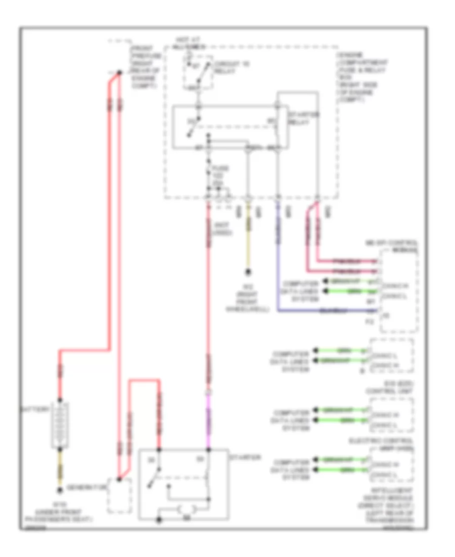
Starting Wiring Diagram for Mercedes-Benz R500 2007
List of elements for Starting Wiring Diagram for Mercedes-Benz R500 2007:
- (not used)
- 87a
- Battery
- Can-c h
- Can-c l
- Circuit 15 relay
- Computer data lines system
- Eis (ezs) control unit
- Electric control unit (vgs)
- Engine compartment fuse & relay box (right side of engine compt)
- Front prefuse (right rear of engine compt)
- Fuse 25a
- Generator
- Hot at all times
- Intelligent servo module (direct select) (left rear of transmission housing)
- Me-sfi control module
- Mr1
- Mr2
- Mr3
- Mr4
- Red
- Starter
- Starter relay
- W10 (under front passenger's seat)
- W2 (right front wheelwell)