STARTING/CHARGING
Charging Wiring Diagram for Mercury Tracer GS 1998

List of elements for Charging Wiring Diagram for Mercury Tracer GS 1998:
- (escort zx2)
- (escort/tracer)
- Battery
- C108
- C153
- C156
- C157
- C159
- C160
- C252
- C253
- C260
- Charge indicator
- Engine compartment fuse box
- Fuel injector fuse 30a
- G112 (near starter motor)
- Generator
- Ground distribution system
- Hot in run or start
- I/p fuse panel
- Instrument cluster
- Main fuse 100a
- Meter fuse 10a
- Nca
- Ohms
- S220
- Starter assembly
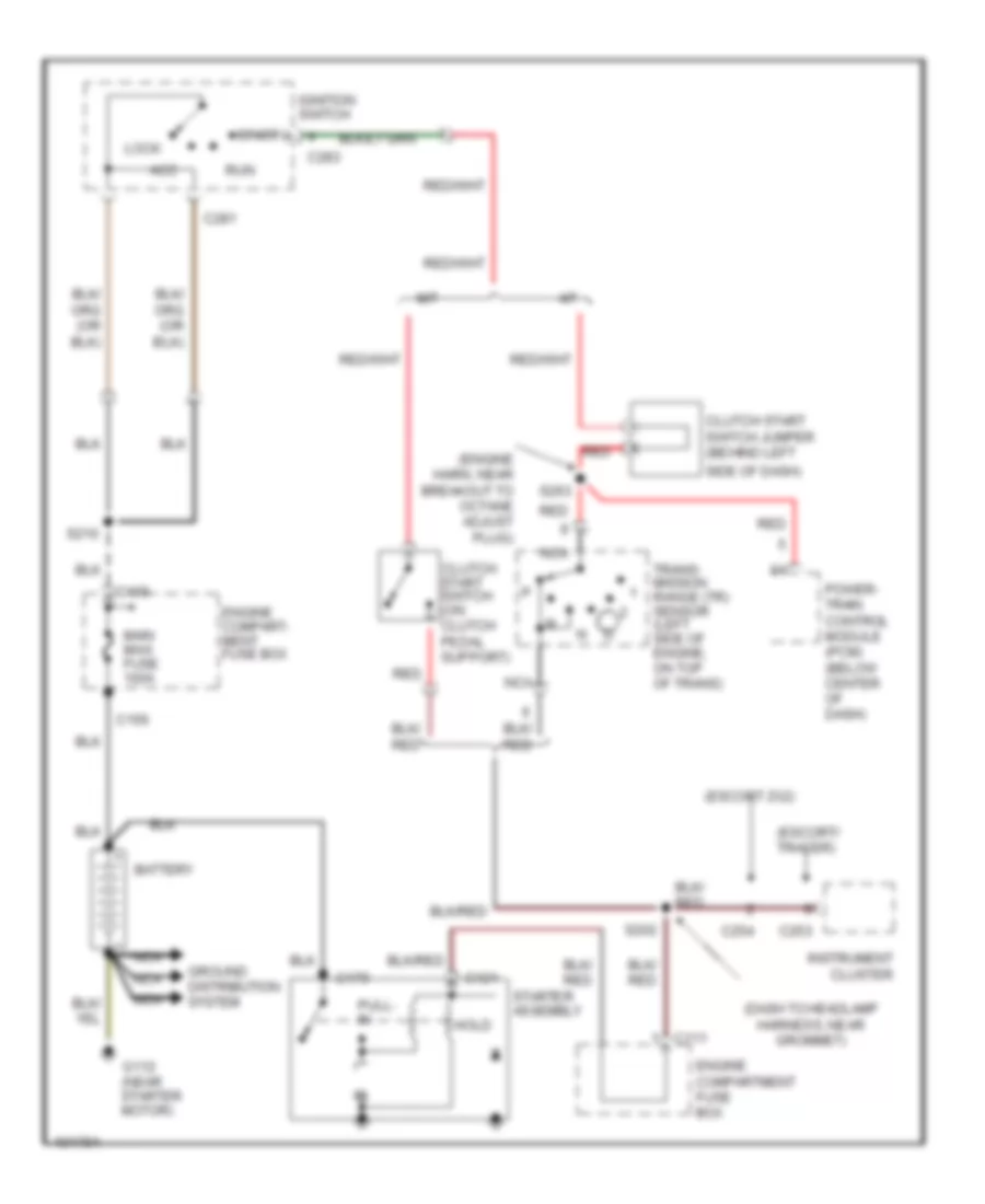
Starting Wiring Diagram for Mercury Tracer GS 1998
List of elements for Starting Wiring Diagram for Mercury Tracer GS 1998:
- (dash to headlamp harness, near grommet)
- (engine harn, near breakout to octane adjust plug)
- (escort zx2)
- (escort/ tracer)
- A/t
- Acc
- Battery
- C109
- C111
- C121
- C156
- C179
- C253
- C254
- C281
- C283
- Clutch start switch (on clutch pedal support)
- Clutch start switch jumper (behind left
- Engine compart- ment fuse box
- Engine compartment fuse box
- G112 (near starter motor)
- Ground distribution system
- Hold
- Ignition switch
- Instrument cluster
- Lock
- M/t
- Main maxi fuse 100a
- Nca
- Power- train control module (pcm) (below center of dash)
- Pull- in
- Red
- Run
- S202
- S210
- S263
- Side of dash)
- Start
- Starter assembly
- Trans- mission range (tr) sensor (left side of engine, on top of trans)