STARTING/CHARGING
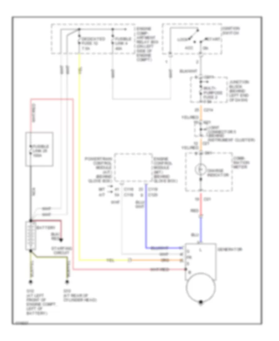
Charging Wiring Diagram, Evolution for Mitsubishi Lancer ES 2003

List of elements for Charging Wiring Diagram, Evolution for Mitsubishi Lancer ES 2003:
- 40a
- 7.5a
- Acc
- Battery
- C01
- C119
- C211
- C214
- C23
- Charge indicator
- Comb- ination meter
- Dedicated fuse 12
- Engine comp- artment relay box (on left side of engine compt)
- Engine control module (behind glove box)
- Fuse 2 7.5a
- Fusible link 26 100a
- Fusible link 4
- G10 (at lower left rear of engine)
- Generator
- Ignition switch
- Joint connector 4
- Junction block (behind left end of dash)
- Lock
- Nca
- Red
- Start
- Starting circuit
Charging Wiring Diagram, Except Evolution for Mitsubishi Lancer ES 2003
List of elements for Charging Wiring Diagram, Except Evolution for Mitsubishi Lancer ES 2003:
- 40a
- 7.5a
- A/t
- Acc
- Battery
- C01
- C118
- C119
- C120
- C21
- C211
- C214
- Charge indicator
- Comb- ination meter
- Dedicated fuse 12
- Engine comp- artment relay box (on left side of engine compt)
- Engine control module (m/t) (behind glove box)
- Fusible link 26 100a
- Fusible link 4
- G10 (at rear of cylinder head)
- G12 (at left front of engine compt, left of battery)
- Generator
- Ignition switch
- Joint connector 5 (behind instrument cluster)
- Junction block (behind left end of dash)
- Lock
- M/t
- Multi- purpose fuse 2 7.5a
- Nca
- Powertrain control module (a/t) (behind glove box)
- Red
- Start
- Starting circuit
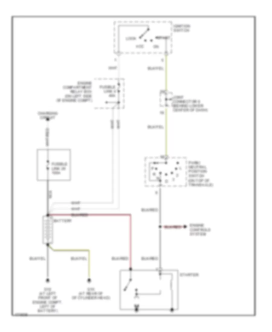
Starting Wiring Diagram, A/T for Mitsubishi Lancer ES 2003
List of elements for Starting Wiring Diagram, A/T for Mitsubishi Lancer ES 2003:
- (on top of transaxle)
- Acc
- Battery
- Charging circuit
- Engine compartment relay box (on left side of engine compt)
- Engine controls system
- Fusible link 26 100a
- Fusible link 4 40a
- G10 (at rear of of cylinder head)
- G12 (at left front of engine compt, left of battery)
- Ignition switch
- Joint connector 6 (behind lower center of dash)
- Lock
- Nca
- Park/ neutral position switch
- Start
- Starter
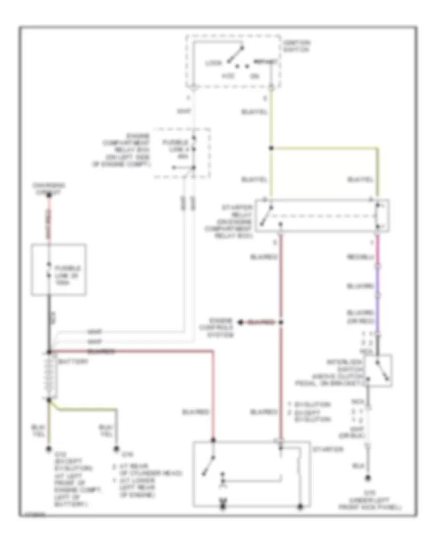
Starting Wiring Diagram, M/T for Mitsubishi Lancer ES 2003
List of elements for Starting Wiring Diagram, M/T for Mitsubishi Lancer ES 2003:
- (at left front of engine compt, left of battery)
- (or red)
- Acc
- At rear
- Battery
- Charging circuit
- Engine compartment relay box (on left side of engine compt)
- Engine controls system
- Evolution
- Except evolution
- Fusible link 26 100a
- Fusible link 4 40a
- G10
- G12 (except evolution)
- G15 (under left front kick panel)
- Ignition switch
- Interlock switch (above clutch pedal, on bracket)
- Left rear of engine)
- Lock
- Nca
- Of cylinder head) (at lower
- Start
- Starter
- Starter relay (on engine compartment relay box)