AUTOMOTIVE ELECTRICIANS PORTAL

STARTING/CHARGING – Mitsubishi Lancer GTS 2008 – SYSTEM WIRING DIAGRAMS

STARTING/CHARGING

Charging Wiring Diagram for Mitsubishi Lancer GTS 2008

Charging Wiring Diagram for Mitsubishi Lancer GTS 2008 https://portal-diagnostov.com/license.html
https://portal-diagnostov.com/license.html Automotive Electricians Portal FZCO Automotive Electricians Portal FZCO
Download PDF file

List of elements for Charging Wiring Diagram for Mitsubishi Lancer GTS 2008:

  • (generator malfunction light)
  • 120a
  • 7.5a
  • B-108 b-09
  • B-109 b-10
  • Battery
  • C-317
  • Can
  • Circuit
  • Combination meter
  • Computer data lines system
  • Cpu
  • Engine compartment fuse/relay box (left side of engine compt)
  • Engine control module (except evolution: left rear of engine compt) (evolution: near relay box)
  • Etacs-ecu (behind left end of dash)
  • Evolution
  • Except evolution
  • Fuse
  • Fuse 5
  • Fusible link 33
  • Fusible link 36
  • Fusible link box (except evolution: next to battery) (evolution: near relay box)
  • G19 (except evolution) (left side engine compt)
  • G21 (evolution) (near battery)
  • G3 (except evolution) (under right front kick panel)
  • Generator
  • Generator malfunction light
  • Hot w/ ig1 relay energized
  • Lcd
  • Led drive circuit
  • Pnk
  • Starting circuit
  • Transceiver

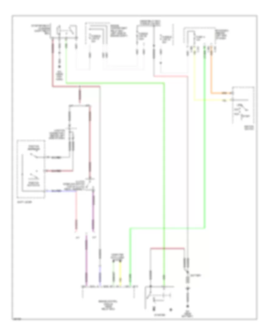
Starting Wiring Diagram, Evolution for Mitsubishi Lancer GTS 2008

Starting Wiring Diagram, Evolution for Mitsubishi Lancer GTS 2008 https://portal-diagnostov.com/license.html
https://portal-diagnostov.com/license.html Automotive Electricians Portal FZCO Automotive Electricians Portal FZCO
Obtenha acesso a todos os diagramas de fiação do carroDownload PDF file

List of elements for Starting Wiring Diagram, Evolution for Mitsubishi Lancer GTS 2008:

  • (near relay box) fusible link box
  • 10a
  • 120a
  • 30a
  • 80a
  • A/t
  • Acc
  • B-09
  • B-10
  • Battery
  • C-304
  • C-309
  • C-315
  • C-317
  • Clutch interlock switch (top of clutch pedal assembly)
  • Computer data lines system
  • Engine compartment relay box (left side of engine compt)
  • Engine control module (near relay box)
  • Etacs-ecu (behind left end of dash)
  • Fuse 14
  • Fusible link 24
  • Fusible link 34
  • Fusible link 36
  • G12 (near high horn)
  • G21 (near battery)
  • Ignition switch
  • Junction connector 7 (behind left side of dash)
  • Lock
  • M/t
  • Position switch (n)
  • Position switch (p)
  • Run
  • Shift lever
  • Start
  • Starter
  • Starter relay (in engine compt relay box)

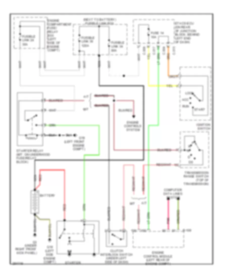
Starting Wiring Diagram, Except Evolution for Mitsubishi Lancer GTS 2008

Starting Wiring Diagram, Except Evolution for Mitsubishi Lancer GTS 2008 https://portal-diagnostov.com/license.html
https://portal-diagnostov.com/license.html Automotive Electricians Portal FZCO Automotive Electricians Portal FZCO
Obtenha acesso a todos os diagramas de fiação do carroDownload PDF file

List of elements for Starting Wiring Diagram, Except Evolution for Mitsubishi Lancer GTS 2008:
  • (next to battery) fusible link box
  • 10a
  • 120a
  • 30a
  • 80a
  • A/t
  • Acc
  • B-109
  • Battery
  • C-304
  • C-309
  • C-315
  • C-317
  • Clutch interlock switch (under left side of dash)
  • Computer data lines system
  • Engine compartment fuse/ relay box (left side of engine compt)
  • Engine control module (left rear of engine compt)
  • Engine controls system
  • Etacs-ecu (on rear of junction block, behind left end of dash)
  • Fuse 14
  • Fusible link 24
  • Fusible link 34
  • Fusible link 36
  • G18 (left front engine compt)
  • G19 (left side engine compt)
  • G3 (under right front kick panel)
  • Ignition switch
  • Lock
  • M/t
  • Nca
  • Pnk
  • Red
  • Run
  • Start
  • Starter
  • Starter relay (m/t: on underhood fuse/relay block)
  • Transmission range switch (top of transmission)