STARTING/CHARGING
Charging Wiring Diagram for Mitsubishi Lancer Ralliart 2010

List of elements for Charging Wiring Diagram for Mitsubishi Lancer Ralliart 2010:
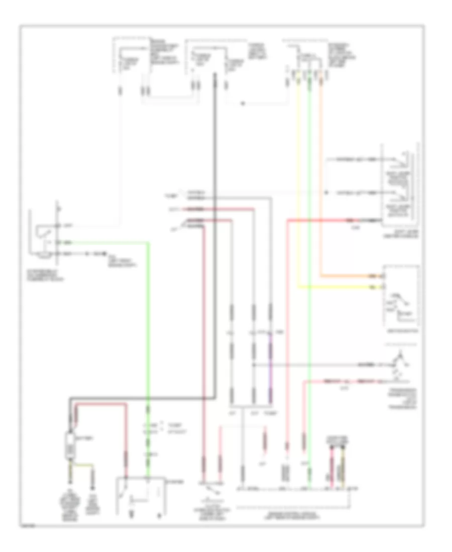
Starting Wiring Diagram, Evolution for Mitsubishi Lancer Ralliart 2010
List of elements for Starting Wiring Diagram, Evolution for Mitsubishi Lancer Ralliart 2010:
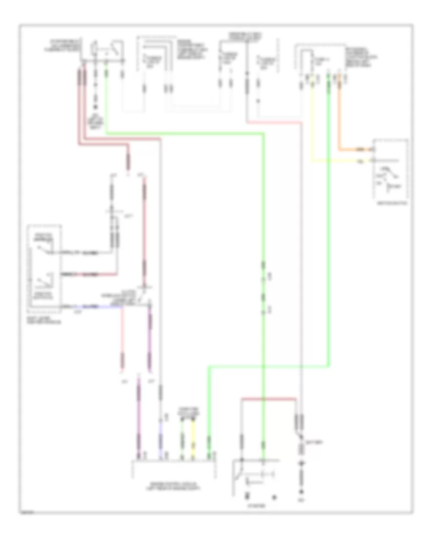
Starting Wiring Diagram, Except Evolution for Mitsubishi Lancer Ralliart 2010
List of elements for Starting Wiring Diagram, Except Evolution for Mitsubishi Lancer Ralliart 2010: